This thread has been locked.

If you have a related question, please click the "Ask a related question" button in the top right corner. The newly created question will be automatically linked to this question.

Terminations for SN65HVD1780 RS485

I  need to know if I need to add anymore termination components to the front end of my RS485 system?

Already using common mode filter, Bi-Direction TVS on each line and between the lines and ferrite beads inline with A and B lines on all nodes.

# of Nodes: 40

Baud Rate: 38.4K

Total Buss Length:  6000ft

Thanks,

Tim

  • Tim,

    yes you will need termination at both cable ends. The need for termination depends on the fastest signal on your bus. This is not the actual data rate but the driver rise/fall times which, for the HVD1780, are 400 ns minimum. A rule-of- thumb is to apply termination once your round-trip delay is longer than 1/10th of the rise/fall time. This limits the round-trip delay to 40ns if you were working without termination.

    However, your bus length is 6000 ft, which makes the roundtrip length twice as much: 12000 ft (or ~4000m). With a typical propagation-delay of 5ns/meter, the round-tri delay becomes 20,000 ns or 20 us. this means that 20 us after the first falling edge of your start-bit, its reflection hits right into the middle of one of the following data bits. And because of no termination this reflection will bounce forward and back until its energy dies out.

    Now there will be many more of these reflections, in fact each bit transition will cause and endless stream of reflections bouncing for and back.

    Placing termination resistors (whose values must match the characteristic cable impedance) both ends of the bus will absorb the energy of the signal waves in these resistors and therefore preventing reflections.

    Hope this helps.

    Best regards, Thomas

  • Thomas,

    I will specify termination resistors.

    On a similar note, I have seen a design that incorporates a series RC between the A and B lines.  Have you ever seen this?  The fc is set for 2x the baud rate.  Would this relieve the need for termination resistors?

    Thanks,

    Tim

  • Tim,

    if you go with 120 ohm resistors, one at each end you come pretty close to most cables out there. even 18 AWG lamp cable comes close to 140 ohms Zo.

    The R-C you were mentioned is known as AC termination. It basically terminates the bus during signal transitions and saves dc-power during the steady state of a bit due to the capacitor. I have seen it in some applications but it seems to pretty much butcher signals more than it does good. The capacitor value not only depends on the data rate, but also on the bus lengths and the number of bus nodes. So if you have a bus installation no one will ever extend or add network nodes to it, go and try it out.

    I prefer the standard, parallel termination of 100 to 120 ohm resistors at each end. It makes life so much easier.

    Regards, Thomas

  • Thomas,

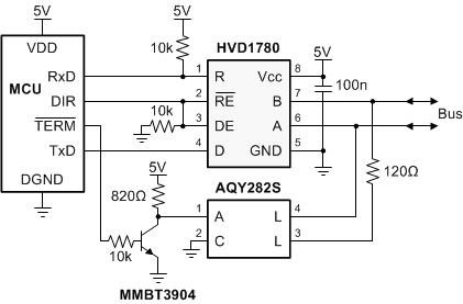
    Can you recommend or point me to any reference designs using an FET or photo FET to switch in/out the termination resistors across the A/B lines?  Can this be done? Any drawbacks?

    Looking for a solution that doesn't require manual insertion of a jumper or resistor.

    Thanks,

    Tim

  • Tim,

    below is an example of a switchable termination using a Photo Relay. Its input LED is driven with an NPN as I don't know whether your controller has the drive capability to drive the LED directly. Because of the NPN the TERM output becomes low-active, hence /TERM.

    Hope this is what you're looking for.

    Regards, Thomas

  • Thanks,  That will do nicely!

    Tim Decker

  • Tim,

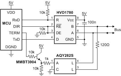
    I just checked. The circuit below should also work. This one allows for TERM to be active-high.

    regards, Thomas