RS-485 Loss-Of-Signal (LOS) Indicator distinguishes between failsafe-high and data-high
This post shows you how to build your own, simple and effective, Loss-Of-Signal indicator
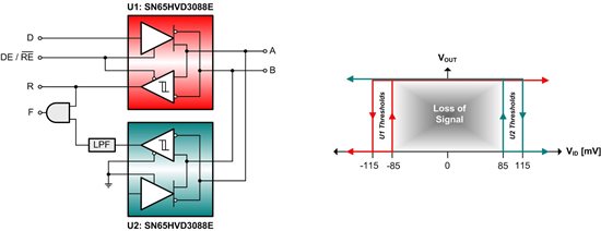
Formerly RS-485, EIA/TIA 485 specifies its receiver input thresholds with ±200 mV. For signals above 200 mV, the receiver output becomes logic high. Signals below –200 mV become logic low. For signals in between, the output state is undefined. Modern transceivers featuring integrated failsafe biasing have their input threshold voltages offset into the negative voltage range, thus driving the receiver output high when the input signal exceeds an upper negative threshold. See U1 thresholds in Figure 1.
A slight drawback is that the processing logic following the receiver cannot easily differentiate between a high caused by the loss of an input signal and a high representing valid data. A simple do-it-yourself loss-of-signal (LOS) indicator, however, overcomes this lack of differentiation by providing a separate LOS-flag in addition to the receiver output state.
Figure 1 shows the LOS indicator circuit with its associated transfer functions on the right. The design requires two transceivers. The first is a primary transceiver taking care of the standard data traffic and indicating signal voltages higher than –85 mV. The second is a transceiver with reversed input polarity, indicating voltages below +85 mV. AND-gating both receiver outputs causes output fault (F) to assume logic high for voltages between –85 mV and +85 mV. Thus, indicating the loss of an input signal.
Figure 1. LOS Indicator with Transfer Function
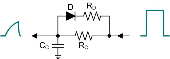
To avoid F becoming high during normal signal transitions, low-pass filtering (LPF) of the second receiver output is required. Hence, only indicating low-voltage conditions of sufficient duration.
Figure 2. Low-Pass Filter with Accelerated Discharge
In addition to the simple R-C low-pass creating the necessary delay, the resistor –diode path parallel to RC provides fast and complete discharge of CC before the next signal transition. See Figure 2.
Note that the combination of the one-eighth unit load transceivers above increases the unit loading per node to one-fourth UL. Thus, allowing for a total number of 128 nodes featuring LOS indication while complying to EIA/TIA 485.
Hope you enjoy building it. Best regards, Thomas


