This thread has been locked.

If you have a related question, please click the "Ask a related question" button in the top right corner. The newly created question will be automatically linked to this question.

AM26C32 Latch stuck differential high or low to unlatch with ACS controller SPIIplus SA 8

Other Parts Discussed in Thread: AM26C31

Hello all,

Hope someone can help with this one. We are having an issue with our differential outputs and registering our single ended input device.  
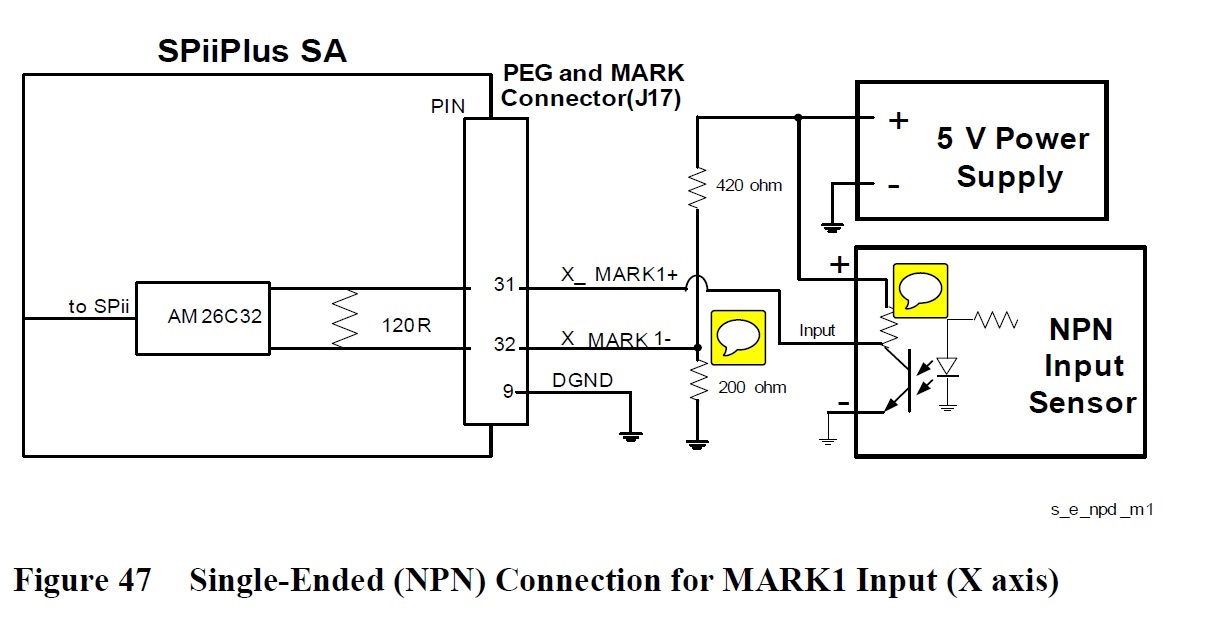
We cannot figure out the Vid or if this is enabled on Voh or Vol...  The table on the RS422 compatability is as follows.

Any help would be greatly appreciated as we are dead in the water right now.

Thank you,

Rudy

  • Rudy,

    The 1- input drive is 1.6V at 135 ohms per Thevenins formula. Vth = 5V * (200/620)  Rth = 1 (1/200 + 1/420)

    A really good sensor transistor on voltage will be near 0V.

    This makes IN+ 0V and IN- at 120/(135+120)*0.6V = 0.753V
    Total VID is -0.75V; this is well under recommended 2V VID.

    A transistor off voltage will be near 5V through an unlabeled resistor, I will call 'R'.

    This makes VID+ = 120 ohm / (120 ohm + 135 ohm + R) * (5V - 1.6V)
    if R was very low like 50 ohms then VID+ = 1.34V which is also low. >2V is desired.

    If the cable was short and the data rate was slow, the system would work, but it can and should be improved.

    What is the resistor value in the sensor?
    What is the maximum recommended sink current for the sensor?
    What is the cable length and data rate?

    With this information, I can help you better.

  • Ron,

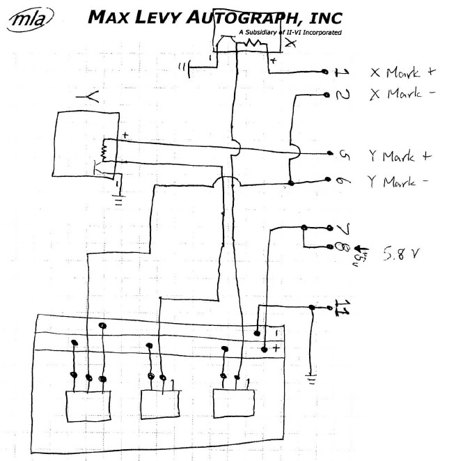
    Thank you for your response.  I will try to provide as much information as possible on our setup and hope it will be enough.  We have a breadboard setup for the circuit in the diagram with 3x 500 Ohms potentiometers.  I have a hand drawn diagram (sorry for the quality) that is below.

    This is the actual picture.

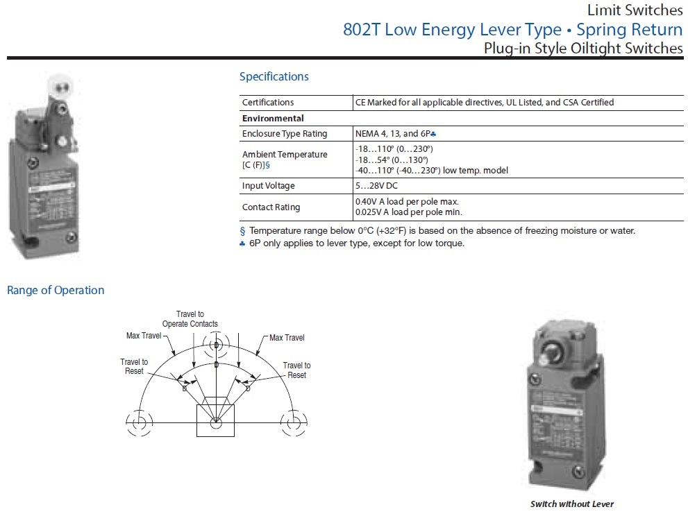
    I looked up our sensor and have attached their spec data here.

    That is the complete circuit leading into the ACS controller.  Just as a scenario we have it currently with the following voltages.

    x_mark+       2.7v

    x_mark-        1.8v

    after sensor is tripped...

    x_mark+       0v

    x_mark-        0.9v

    Again thank you for your help and time, I am at a loss when it comes to this.

    Thank you,

    Rudy Smith

  • Rudy,

    I can help you. My suggested plan added a AM26C31 as a driver to get a good differential signal.
    If that puts the project over cost , then I will try something else.

    I looked at the limit switch and it doesn't have a pull up resistor. It should have 4 or 8 switch contact connections.
  • I believe this is going to be the answer but unfortunately I will not be able to test this out until later. Our controller took a dive on us and It is being repaired. Thank you for all of your help on this and I purchased the AM26C31CN to be put in the breadboard and wired up. Now it's just a waiting game.