This thread has been locked.

If you have a related question, please click the "Ask a related question" button in the top right corner. The newly created question will be automatically linked to this question.

SN65HVDA100-Q1 / About supply current.

Other Parts Discussed in Thread: SN65HVDA100-Q1

Hi all.

I have two questions about the supply current of SN65HVDA100-Q1.

The data sheet P.12 shows the supply current in the case of 4.10 .
I would like to know the supply current of sleep mode at 14V<Vsup<27V,LIN=0V,
NWakw=Vsup,EN=0V,TXD and RXD floating.
This value is very important for our customer to select the LIN transceiver.
Our customer expects Isup(4.10)<50uA.

And please tell me the calculating formula of Isup.
Can we calculate the Isup by the formula of note(3)?


Best Regaeds,
Sho Ogane

  • Hi Sho,

    Thanks for your post.

    I will check with our team, if there have been taken any measurements for the supply current with your desired conditions in the past.
    If not, I will set up a test in our lab and take some measurements for you.

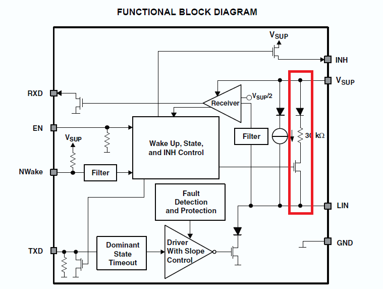
    The formula under (3) is only for normal and standby mode. The difference to the sleep mode is that the internal bus termination is still active and  therefore the current consumption for normal and standby mode will be higher. You can see the internal termination in the functional block diagram too.

    You can expect a much lower current consumption for sleep mode and LIN at 0V.

    I will come back to you as soon as I have got some more details on that.

    Best regards,
    Chris

  • Hi Chris san.

    Thank you for the reply.

    OK! Thank you!
    I wait the data or the test result from you.

    And I understood about the fomula under (3).
    I will check the block diagram and note(3).

    Best regards,
    Sho Ogane  

  • Hi Chris san.

    I would like to tell the result to our customer as soon as possible.
    So, please help us.

    Best Regards,
    Ogane Sho

  • Hi Sho san,

    unfortunately we don't have the required data in our system.
    I will set up a test in our lab today and come back to you with the results.

    Best regards,
    Chris

  • Hi Sho san,

    I have tested two of our devices in sleep mode with LIN at 0V.
    As an estimate for the supply current values under the desired conditions you can use this formula: Isup = (Vsup-Vlin+0.7V) / 65kOhm.

    So you can see that the supply current will be higher than your limit of 50uA. For a floating LIN pin the SN65HVDA100-Q1 will still meet the Vsup <= 30uA spec for the test conditions under 4.10 in the datasheet.

    Do you know the exact scenario in your customer application that sets the requirement for a supply current less than 50uA in sleep mode and with LIN at 0V?
    If there will be a transition from a high LIN state to low (dominant) and the dominant state will be applied for a time equal or longer than t(LINBUS) this would generate a wake-up condition anyhow (figure 5 on page 8 of the datasheet).

    Best regards,
    Chris

  • Hi Chris san.

    Thank you for the reply.

    I think that the resistor of 65kΩ is the value of the internal pull-up resistor.
    Does the value of the pull-up resistor change to 65kΩ from 30kΩ when this device is sleep mode?
    And does the device change the resistor by the mode(e.g. sleep mode, normal mode, stanby mode)?

    I asked the reason that my customer sets the requirement for a supply less than 50uA in sleep mode and LIN at 0V.
    My customer's application is the control panel of air conditioner.

    The master and the slave of this application are different ECUs(Engine Control Unit). 
    Therefore, there is difference of voltages between the master and the slave.
    My customer have received a request value of leakege current from the END user .
    My customer ask me the worst case (Vlin=0V).
    My customer assumes Vlin=Vsup-3V.

    Please tell me the solution that the value of Isup become below 50uA.

    Best Regards,
    Ogane Sho

  • Hi Sho san,

    in normal and standby mode the SN65HVDA100-Q1 uses the 30kΩ termination resistor with the series switch you can see in the graphic above. In parallel to this structure this device has the weak pull-up for the sleep mode which is represented by the 65kΩ resistor, so in normal and standby mode you will have these both resistors in parallel which result in the 20kΩ you can find in the equation to calculate the supply current mentioned in your first post.

    If you need the wake-up by bus signal feature there is no reasonable way to decrease the current consumption in the sleep mode. Else you could power down the device and use a separate device for the wake-up.

    Under the common operating conditions (with Vlin = Vsup -3V) you will have no problems with the supply current requirement.


    Best regards,
    Chris

  • Hi Chris san.

    Firstly, I apologize for the delay in replying to you.

    I know this device has the normal mode, the standby mode, the sleep mode.
    If this device is the normal mode or the standby mode,we can calculate the conbined resistor (30kΩ and 65kΩ), this value is 20kΩ.
    If this device is sleep mode, the termination resistor is 65kΩ.
    So, does it not become acondetion of 30kΩ basically?

    And the datasheet P13.7.15 shows that the value of Rslave changes 20kΩ(min) to 60kΩ(max).
    You said this device has 65kΩ resistor, Are 60kΩ resistor and 65kΩ resistor related?  

    Best Regards,

    Sho Ogane

  • Hi Sho san,

    thanks for your answer.

    The internal resistors in integrated circuits may vary due to the manufacturing process. This is why the pull-up resistor under 7.15 in the datasheet is specified to be 20kΩ to 60kΩ (typical 30kΩ). This is only the "active" pull-up in normal and standby mode. This termination is deactivated in sleep mode and only the 65kΩ (typical) pull-up resistor remains.

    A 30kΩ condition could arise due to the variation in the resistor values.  

    Best regards,
    Chris

  • Hi Chris-san,

    I'm Sonoki working with Sho in disty in Japan. As you discussed with him, our has concerning about sleep current at low LIN bus condition. Can you take example data of sleep current with following condition?

    • VSUP = 12V
    • LIN = 2V
    • NWake = VSUP
    • EN = 0 V
    • TXD and RXD floating

    Best Regards,

    Sonoki / Japan Disty

  • Hi Sonoki,

    Chris has deployed in to his final role at TI and is no longer with the interface team. My name is Mike and I will be supporting this request moving forward.

    Tomorrow I will check the conditions outlined above on the bench and provide you feedback.
  • Hi Mike,

    I appreciate for your effort for my request. I'm looking forward to you feedback.

    Best Regards
    Sonoki
  • Hi Sonoki,

    I'm Vio Liu working with Christian. Christian will work in Germany so i will follow this question. I will test the data so soon as possible.

    Best regards,
    Vio Liu
  • Hi Vio Liu,

    Thank you for your support. I'm waiting for your update.

    Best Regards,
    Sonoki
  • Hi Vio Liu,

    Thank you for your support. I'd like to have your update within this week your time to respond our customer early next week.

    Best Regards,
    Sonoki
  • Hi Satoshi,

    Sorry for the late reply because i need some to hand over and the characteristic board has lots of jumpers but there's no  documents or schematics^_^

    The test result is 241.3 uA in sleep mode and 727.8 uA in normal mode, 726.9 uA in standby mode.

    If there's any questions you're welcome to ask. I think i can answer your question timely now^_^

    Best regards,

    Vio Liu

  • Hi Vio Liu,

    I really appreciate for your support. This information will be very helpful for our customer.

    Best Regard,
    Sonoki