This thread has been locked.

If you have a related question, please click the "Ask a related question" button in the top right corner. The newly created question will be automatically linked to this question.

TRS213C Fail issue

Other Parts Discussed in Thread: TRS213

Dear Sir 

Our customer use their RS232 Barcode Scanner with TRS213C ,The Barcode function is not workable

But Our customer change to use ADM213E (due to the schematic and package is the same) ,The Barcode function  is workable

(This issue only happened with this Barcode scanner )

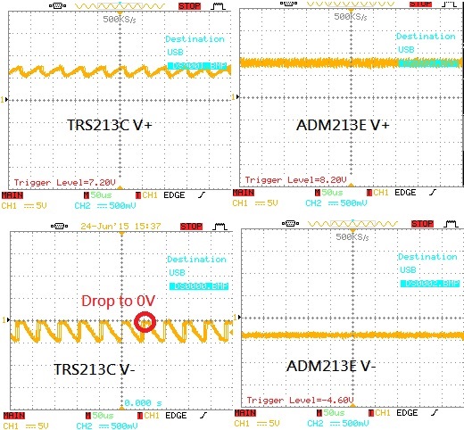
Our customer find our TRS213C's V+(Pin13) and V-(Pin17) voltage are abnormal 

Could you kindly help to give more detail information about this issue? Do you have any suggestion could solved this issue??

Thanks


  • Dear Kai Hsiao,

    thank you for providing these scope shots. The negative V- voltage looks pretty strange. The datasheets, page 5 specifies a voltage V- < -5V, which in your case is obviously not the case. The load for the specification is 3 kohm to GND.
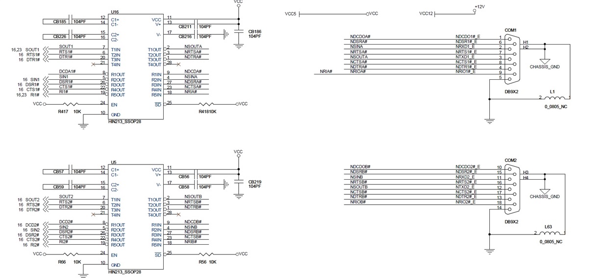
    How big is the load in this application, how much current is drawn? Are there four 100nF caps applied to C1+/-, C2+/-, V+ to Vcc, V- to GND? Is the polarity of the cap between V- and GND correct? If the cap is applied in the wrong direction, it might not function correct.
    Could you provide us a schematic for review to help you with your problem?

    Best Regards
    Till
  • Dear Jonas

    1. I don't have idea about the output load ,If I use RS232 loopback tool and windows Burn-in test S/W to verify ,it is workable ,but if I use the end customer RS-232 scanner ,TRS213C is unworkable ,Could you kindly teach me how to verify the load ? 

    2.Below is our schematic ,I pop TRS213C and ADM213E at the same time on this PCB and change the location ,It's problem will follow TRS213C  

  • Kai,

    The load is greater than the RS232 standard allows. This lowers the output voltage. Because the voltage is low, the bar code scanner malfunctions and shorts the TRS213 driver outputs then resets.

    TRS213 has a 100% duty cycle low frequency charge pump. The capacitors need be increased to support the extra load. Values up to 1uF are acceptable.

    The ADM213 appears to run at a higher frequency. This wastes power, but helps support more output drive.
  • Dear Michallick

    Thanks for your reply 

    1.This lowers the output voltage. Because the voltage is low => I don't understand your means ,could you kindly help to enplane more information

    2.You mean change to use charge pump cap from 0.1uF to 1uF ? Due to 0.1uF is recommend from datasheet ,if all of project change to use 1uF ,have any side effect about TRS213C or something else?

    I will verify 1uF solution ,hope we can get good news

    Thanks

  • Dear Michallick

    One more question 

    You mean extra capacitor change to use 1uF ,which one change to 1uF?? only charge pump cap or include V+/V- Cout??

    Total 4pcs ??

    Thanks

  • Kai-san,

    C1, C2, V+ and V- caps. 4 in total.
    If that works, I will check into any concerns with the capacitor size.