This thread has been locked.

If you have a related question, please click the "Ask a related question" button in the top right corner. The newly created question will be automatically linked to this question.

AM26LV31 driving 3 loads

Other Parts Discussed in Thread: AM26LV31E, AM26LV32E

Hi,

 I am using AM26LV31EIDR (Driver) and AM26LV32EIDR (Receiver) in my design.

I am planning to connect same driver output to 3 Receiver inputs.

Can you let me know, whether AM26LV31EIDR is capable of driving 10 loads as per RS422 Specification?

Can you suggest me, what and all things I need to consider for above implementation?

Regards,

Amith Bhat

  • Amith.

    Yes 10 loads are possible.
    The the driver connects to one end of cable. The cable connect to all three receivers with a termination resistor at the end of the cable.
    Like this; DRIVER-------------RX1------------------RX2-------------------RX3-100ohms (in a chain, no splits)
  • Dear Ron,

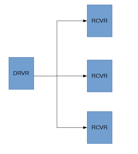
    I was planning to do the connection as star topology, with termination at each receiver (Attached Snapshot)

    What are the concerns in above topology?

    Regards,

    Amith Bhat

  • Amith,

    The total receiver load is the same in the star topology.
    However, the cable impedance seen by the driver is now 1/3. This is too much load.

    RS485 drivers can driver two cables because they can drive from the middle of a cable. Most RS485 IC's are single channel devices. Probably not the right answer.

    I suggest three AM26LV31E one for each star line.
  • Hi Ron,

    To be descriptive, I have 15 Tx channels and 50 Rx channels in my card. All the receivers are provided with 100Ohm termination.

    I want to test my design by feeding RS422 signals to Rx channels.

    Instead of generating RS422 signals outside, I thought of looping back on card Tx channels with Rx channels in 1:3 manner.

    I can not go with daisy chain topology (As per your suggestion) as the receiver IC's are already placed in card.

    Now I have to go with 1:1 loop back for testing the interface, which increases my design and testing work 3 times.

    Can you please suggest any alternative.

    Regards,

    Amith

  • Amith,

    Do you need to check all the receivers with data (at normal speed)?
    Would a simple high / low functional check be OK for "extra" RX channels?
  • Dear Ronald,

    I am sending some pattern through 15 Tx channels. Data rate will be not more than 10Mbps.

    I just want to validate the received data with sent data to verify my design.

    Since there are 50 Receive channels, I do not want to loop back the signal 3 times separately.

    Let me know if you need any further information.

    Regards,

    Amith Bhat

  • Amith,

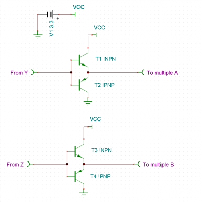
    The simplest solution I see is to build a simple buffer to allow one TX (Y and Z) to drive several A & B inputs with 100 ohms termination.

    This circuit will lose voltage but that makes it a more stringent test.

    VCC can be 3.3V or 5V.

  • Dear Ronald,
    Thanks for the update.
    I will check the feasibility of using buffer for testing purpose.
    My concern is, as I have to design a buffer in general purpose PCB
    This may affect the signal quality at higher data rate.

    If this is the issue, I will design the test setup such that, I will loopback 1:1 manner using less number of cable setup.

    Regards,
    Amith.
  • Dear Ronald,

    I have found another way to test my hardware.

    I am using one of the Tx channel as a Valid signal to capture my loopback data.

    As AM26LV32E device has internal failsafe circuitry built in, will the un-connected Rx channels output will be in 'High' state?

    If the unused Rx channels are in 'High' state, I can send Active Low valid signal from controller to indicate which set of Tx and Rx channels are looped back.

    Please provide your feedback.


    Regards,


    Amith Bhat

  • Amith,

    un-connected channels will output a high logic level.