This thread has been locked.

If you have a related question, please click the "Ask a related question" button in the top right corner. The newly created question will be automatically linked to this question.

CAN Bus with Concerto (SN65HVD232 with F28M35)

Other Parts Discussed in Thread: SN65HVD232

Hi,

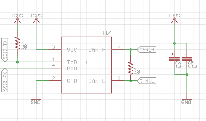
I'm trying to put a few F28M35 concerto devices on a CAN bus. I'm looking at using the SN65HVD232 transceiver for this. Below is my schematic for one of the devices (this is repeated 4 times for the 4 concerto devices):

The traces CAN_H and CAN_L are all connected together on a single PCB. The entire length of the bus will probably be around 20-25 inches maximum.

The SSI0_RX and SSI0_TX lines are directly going to those corresponding GPIO on the Concerto devices.

Does this look correct? Is there anything I should look at or be careful of specifically? The PCB that most of the bus will be routed on is a 2-layer board. I'm not looking at very high bauds for the canbus (1MHz would be faster than I need) so can I get away with that?

Thanks,

Aditya

  • Hi Aditya,

    This implementation looks good to me! One thing to note is that only two of the CAN nodes require the 120 ohm termination resistors. The others will be left unterminated or DNI/DNP. Typically the farthest two nodes are the nodes which receive the termination which reduces the amount of reflections that you will see on the bus preserving signal integrity. Also, if the termination is not right the CAN bus levels will be off which can lead to unwanted behavior.

    On the bus you may want to add places for bus filtering caps (typically 100pF), a common mode choke if EMC is a concern, and a pad site for a bidirectional TVS diode for transient protection. You can make all of these components DNI or DNP but in my opinion placing the pads down is a good idea in case you need to add them later. If you take a look at section 13 in the SN65HVD232 data sheet their are some pointers for bus circuit design and layout guidelines for your reference.
  • Hi,

    Thanks for getting back so quickly! I've taken your advice and added filtering caps and diode protection. I was already looking at that datasheet section but had initially figured I don't need protection for a non automotive application (this will sit in a nice server room). But I like the idea of having it there if I need it.

    Can the CAN bus routing ever be unrecoverable as far as termination goes? Or can I always play with the termination values to get the CANbus going? Again, don't really need super high performance. Slow data rates are completely fine.

    Thanks,

    Aditya

  • Hi Aditya,

    I do not understand you question about the routing being unrecoverable. Please clarify for me?

    The termination resistance should be 120ohms||120ohms giving you an effective impedance of 60ohms. This matches the ISO11898 standard with a tolerance of +/-10%. You can try using different termination resistor values but I really recommend that you stay within the tolerance of the standard. The CAN standard (ISO 11898) requires a minimum differential voltage 1.5V across a 54 ohm load to be compliant. In CAN a differential voltage of 900mV or greater is considered a dominant which gives you ~600mV of headroom to the minimum spec. If you start monkeying with the resistor values you will start to cut in your head room and you could end up with some corner cases that cause you problems.
  • Sorry. I am currently doing this on a 2-layer board so my question was about if there is something I should be shooting for as far as trace impedance as people sometimes suggest with USB and the like. I might have been mixing terms / concepts.

    My total trace length for both CAN_H and CAN_L are around 600mm and the wavelength even at 1MHz is 300000mm, so I'm thinking I should be ok in that respect as long as this termination resistance is 120ohms - is that valid?

    Thanks,
    Aditya
  • Hi Aditya,

    Your target trace impedance should be 120 ohms deferentially for CAN.

    Your wave length is so much longer than your trace length though that I think a mismatch in impedance should be negligible at this data rate. Good design though can never be compromised by surprises so I recommend that you stick to what the ISO 11898 standard recommends.