This thread has been locked.

If you have a related question, please click the "Ask a related question" button in the top right corner. The newly created question will be automatically linked to this question.

SN65HVD251: The problem of difference of time between high level and low level

Part Number: SN65HVD251

Dear,

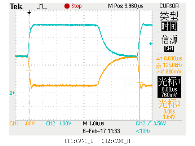
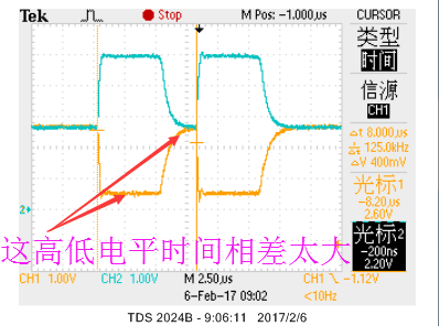
We test SN65HVD251DR and find that the time of high level is 4.6 us and the time of low level is 3.4 us. We hope that when the frequency is 250 KHz, the bit time is 4 us, and the time of high level is equal to the time of low level, the error range of bit time is 0.2% ( the average of tested 10 levels when transmitting data ). So is the next waveform normal? Could you provide the waveform of SN65HVD251DR that TI tested? How to adjust parameters to make the time of high level be equal to the time of low level?

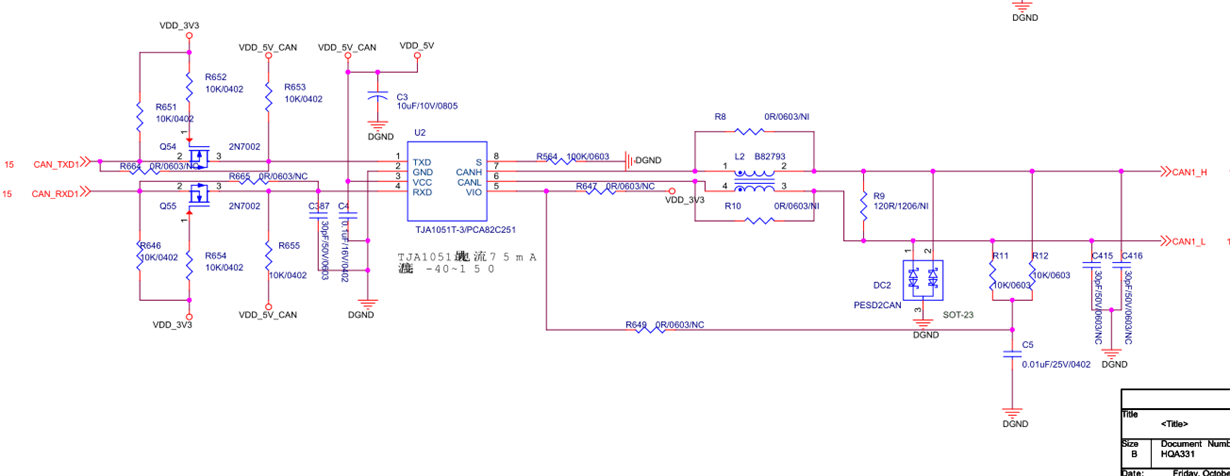
The waveform and the schematic as follows. I am waiting your reply, thank you!

  • Hi Shaw,

    You can see the CAN waveforms of the device operating at 100 kbps in Figure 33 of the datasheet (www.ti.com/.../sn65hvd251.pdf) for reference. In this case it looks like the bit distortion you are seeing is due to the dominant-to-recessive edge taking longer than the recessive-to-dominant edge. Since this edge is not actively driven by the CAN transceiver, its transition time depends on the resistive and capacitive loading on CANH and CANL. When you measured these waveforms, did you have two terminating nodes connected so that the total equivalent resistance between CANH and CANL was 60 Ohms (two 120-Ohm resistors in parallel)? How much capacitance is on the CANH/CANL lines? I saw 30 pF on the schematic - is this accurate? (And if so, how many similar nodes are connected at the same time?)

    Regards,
    Max