This thread has been locked.

If you have a related question, please click the "Ask a related question" button in the top right corner. The newly created question will be automatically linked to this question.

SN65HVD1473: Can be used this IC for RS-422 purpose too?

Part Number: SN65HVD1473

Hi everyone,

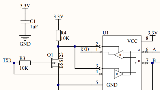
I'm designing a shield board for the Raspberry Pi 3B with the possibility of using RS-485 or RS-422 (With some jumpers) and using a configuration similar to this scheme for activating the transmission pins with a MOSFET transistor (in RS-485 mode):

The question is: Can I use this Ic for RS-422 purpose?

Best regards.

  • Hi Oscar,

    First off I wanted to make sure you are wanting to use the full-duplex, because the schematic you are showing is a half-duplex?

    Also I was wondering what your reasoning was for the FET on the TXD line? As I see it now you will disable the drive whenever you send a high on TXD line, therefore your output state on Y and Z is undetermined so would need some sort of failsafe biasing. And using the device in that way is outside the 485/422 spec for the part.

    As for your question the SN65HVD1473 is RS-422 compatible.

    Regards,

    Daniel Noel 


  • Hi Daniel,

    Thanks in advance for your help and for your quick reply.

    The schematic is only an example how I'm going tu use the RS-485 in half-duplex mode. My goal is design a shield for the raspberry pi (As a Master device) with the following features:

    RS-485(Half-Duplex mode or Full-Duplex mode) or RS-422(Full-Duplex).

    1º.- For RS-485 in half duplex mode I'm going to need the FET in order to desactivate the RX when I need to trasmit data.
    2º.- For Full-Duplex mode (in both RS-485 and RS-422) I'll have to disconect the drain pin of the FET and by default activate both (RX and TX) with pull up and pull-down resistors.

    For RS-485 in Half-duplex I'll have to place a Rt = 120 Ohms.
    For RS-485 in Full-duplex I'll have to place a Rt = 120 Ohms in RX and a a Rt = 120 Ohms in TX.
    For RS-422 in Full-duplex I'll have to place a Rt = 120 Ohms only in RX.

    Best regards.
  • What is the purpose of R3?

    When the receiver is disabled, you need a pull-up resistor on RXD to get a defined level.

    If you have failsafe biasing on the bus, or if all receivers have the idle fail-safe feature, then this scheme might work (for half duplex). However, by never actively driving high bits, you lose of the noise margin of the differential signalling of RS-422.

    There are other circuits that use a monostable to enable the transmitter for a specified time after the start bit. (But this requires knowing the baud rate.)

    The SN65HVD1473 is not full duplex; you'd need separate TX/RX lines for that. Oops, it actually is.

  • Hi Clemens,

    This schematic was copied from the Sparkfun website because they sell a rs-485 shield for Raspberry Pi. You can see in this link the complete schematic: www.sparkfun.com/.../13706

    My target was to have a reference design to use in the RS-485.

    I think the R3 resistor is not necessary.

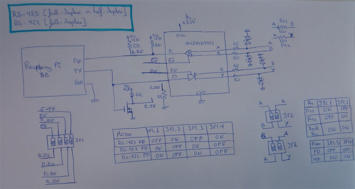
    This is going to be, more or less, the schematic I want to design:

    Best Regards.

  • I do not understand JP2.1/2. Don't they short the differential lines when on?
  • Hi Clemens,

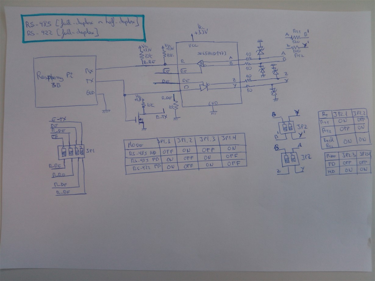
    I made an error. I attached you the new one with everyting fixed:

    Best regards.

  • Moving the switches to the bottom makes it hard to understand.

    Anyway, I see no obvious errors.

  • Hi Oscar,


    1. You do not necessarily need to deactivate the RX line to transmit data in half-duplex mode; your mcu will just be able to hear what it is transmitting, which might be helpful for debugging. As I see it now for JP1 for HD mode you are leaving RE and DE open and that will cause an undefined state on the bus A/B per the function table 1 and table 2, although R will be pulled high because you have a pull up on the line.

    Also I believe your FET is only being tie to R_RE and R_DE when JP1.1/4 are on, and it is not actually controlling RE with your current schematic. 

    2. For your Full-Duplex implementation you have the RE and DE states flipped with the current jumper configuration you have RE high and DE low. RE is active low so you need to tie RE to ground and DE is active high you need to tie DE to VCC unless you are using  a control lines like this:

    So you might want to re-look at your JP1 settings and/or function table


    The way the sparkfun is using the FET to control RE/DE is outside of the normal operation of RS-485/422. Some common ways of configuring RS-485/422 (besides the one above) are like this:


    You might want to look into some of these. For you application I would think the Slave Enable Control config might be the most straight forward one to implement.


    Regards,

    Daniel Noel

  • Hi Daniel,

    Thank you very much for your help.

    1º.- According to 1: "... As I see it now for JP1 for HD mode you are leaving RE and DE open and that will cause an undefined state on the bus A/B per the function table 1 and table 2, although R will be pulled high because you have a pull up on the line...

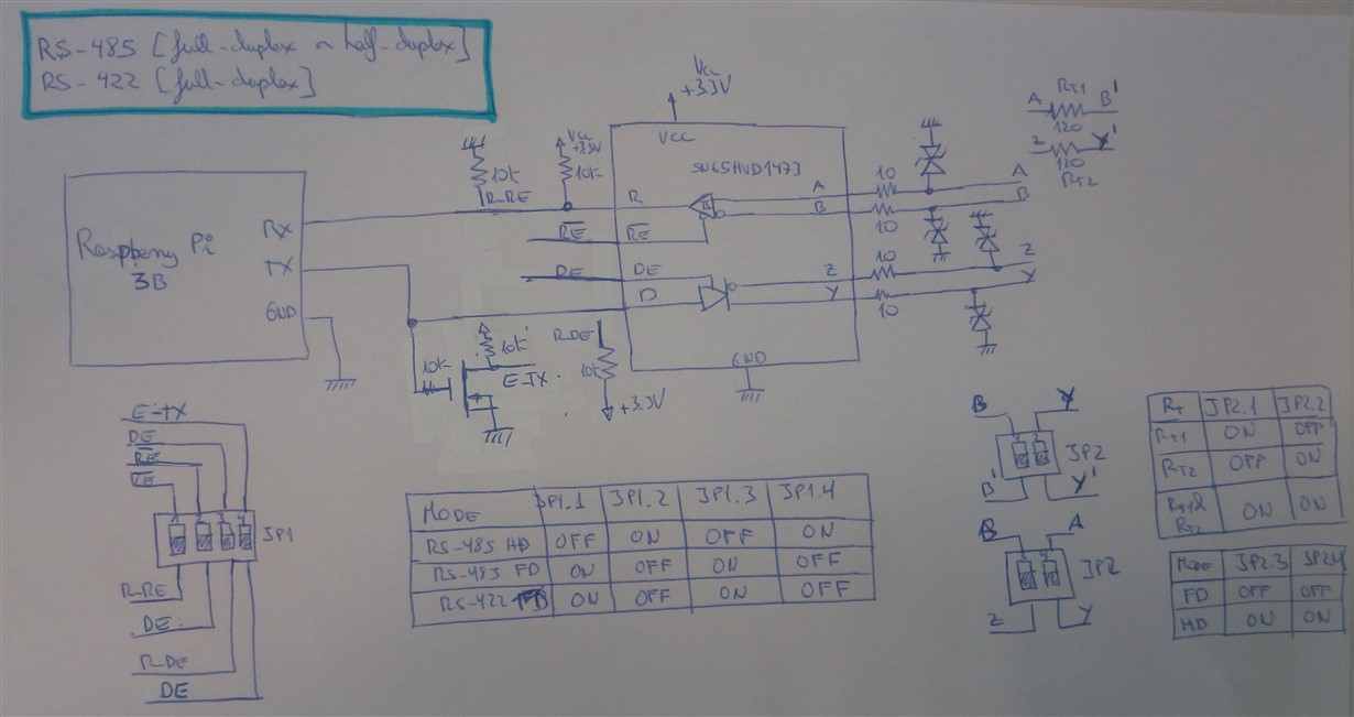
    Yes, I made a mistake. I attached the screenshot fixed.

    2º.- According to 1: "You do not necessarily need to deactivate the RX line to transmit data in half-duplex mode; your mcu will just be able to hear what it is transmitting, which might be helpful for debugging."

    Ok, for debugging it could be a good option. But for normal operation can be a little bit annoyed, can't it?

    3º.- According to: "2. For your Full-Duplex implementation you have the RE and DE states flipped with the current jumper configuration you have RE high and DE low. RE is active low so you need to tie RE to ground and DE is active high you need to tie DE to VCC unless you are using  a control lines like this:..."

    Yes you are right, I made another mistake, so attached you the changes a the screenshot fixed.

    4º.- According to: "...The way the sparkfun is using the FET to control RE/DE is outside of the normal operation of RS-485/422. Some common ways of configuring RS-485/422 (besides the one above) are like this..."

    I think the circuit from Sparkfun is fine due to by default the lines TX and RX are high, so Rx is enabled and the Tx is disabled by default. When Tx start sending data then there is a change in theTX signal (1 -> 0) and in this moment the Rx is disabled and the Tx is enabled. 

    Best regards.

  • Hi Daniel,

    Do you know where I can buy this EVB: www.ti.com/.../TIDA-00892 for testing purpose?

    Best regards.

  • Hi Oscar,


    I am going to follow up with you over email.


    Daniel Noel