This thread has been locked.

If you have a related question, please click the "Ask a related question" button in the top right corner. The newly created question will be automatically linked to this question.

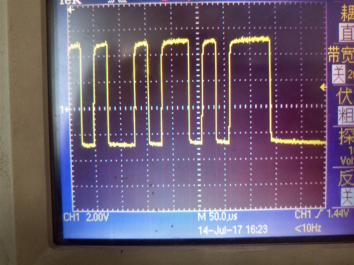
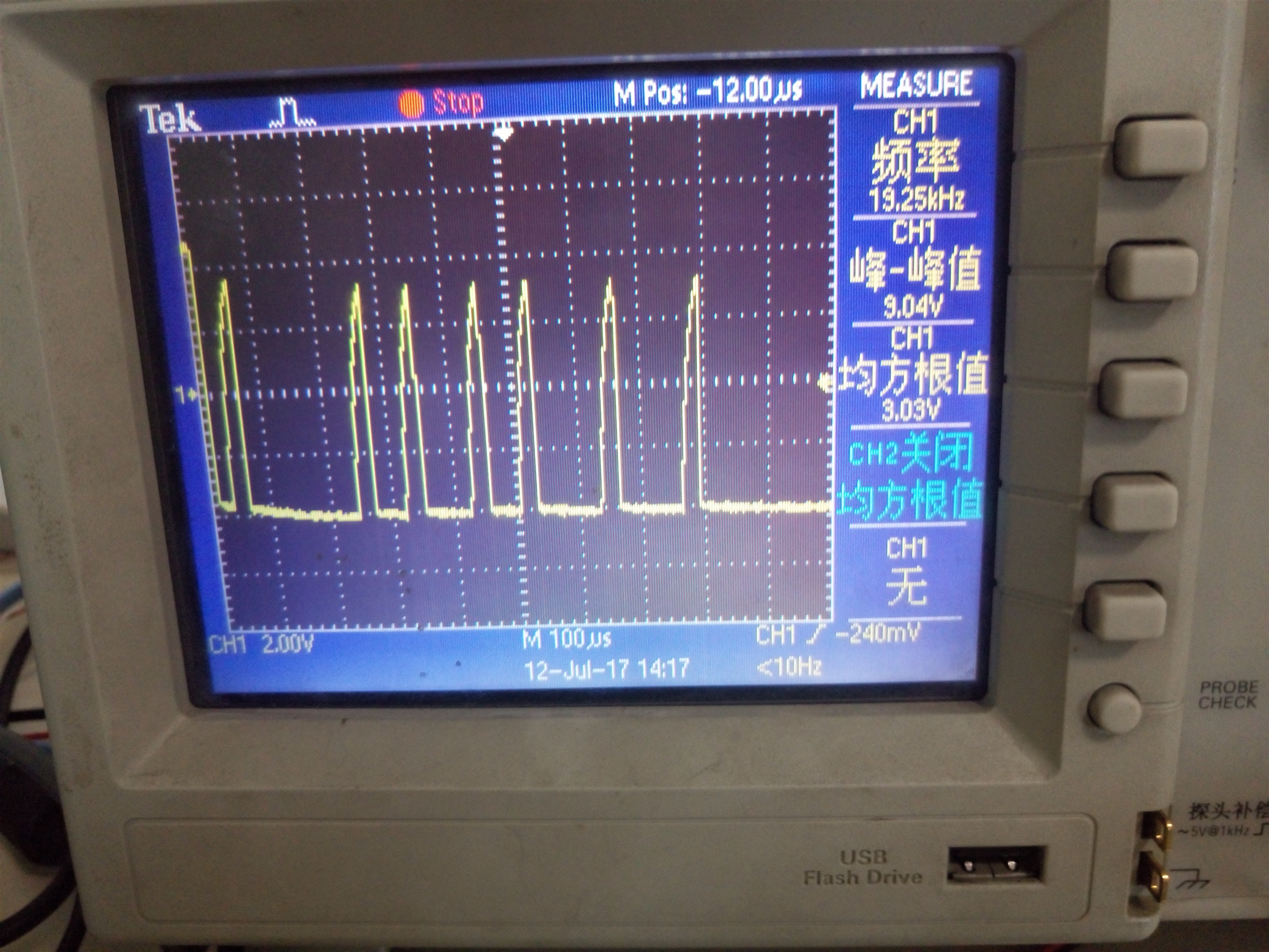
SN65HVD3082 direction controled by BSS138 ,now the scope of AB has a ramp

   my schematic is above ,on board , pin D  continually send data ,now i measure  the differential output of  SN65HVD3082 has a ramp ,please help me 

  • Hello,

    The ramp you see is because the FET circuit you are using disables the output driver (pulls DE pin low) whenever a high level is output (D pin high). You could avoid this entirely by driving DE/RE using a separate, independent signal line so that it remains high for an entire frame/packet duration. If that isn't possible, then you may be able to lessen the effect of the ramp by increasing R154 or adding capacitance to the gate of the FET. This will add some delay between when the D pin is driven high and the DE line goes low. You could also reduce the values of R152 and R153, but this may decrease the overall signal amplitude.

    Max
  •  Thank you very much for your reply!  I have tried to increase R154 to 10k  and  add a 220pf  capacitance between the gate of FET and the gnd ,but it seems to have no effect . finally ,I reduce the values of  R152 and  R153 to 1k ,then  the ramp got disappeared.  So  i have a question  : why is the fist method not effective ? Is the value of  R154 and the 220pf capacitance not right ,or something else? how to choose the value of them?  the scope above is when the R152 and R153  are  all 1k.

  • The purpose of the series resistor and shunt capacitor on the gate of the FET is to add some delay between when the D pin goes high and the DE pin goes low. Could you please check the waveforms at both of these pins and see how much delay is between them? You may need to increase the capacitance further in order to lengthen the delay in order to give the transceiver enough time to fully drive the high level before disabling its output driver.

    Regards,
    Max
  •   still this circuit,ingore the previous question,now R152 and R153 is 2k,and the R158 and R159 IS MOV10D681K , the rate of RS485 is 38400bps,then it can work well ,when I connect rs485 of 27 my devices to simense 485 device(ddc),where the distance between my device and simense 485 is 30cm,and the the distance between my rs485 devices is 30 cm, the simense device can recognize all the 27 mydevice ,but when i extend the distance between my device and simense 485to 400 m impedance of which is 26.3Ω ,then the simense device can only recognize 25 devices through soft on pc . the rate of RS485 is 38400bps,all of above ,there is no 120 temination.what's the reason?could you tell me a method to solve it ?can you reply to me  quickly,I find you answer my question every two day ,hope you can answer me timely,thank you!

  • It is probably a signal integrity issue introduced by the long cables. Is the problem with the two furthest devices on the network? If so, can you configure the bus so that those devices are the ones communicating with the Simense device and measure the waveforms on the A and B lines at each end of the cable? Then we can see what specifically is wrong with the signals and have a better idea what the solution would be.

    Max
  • Hello,max,yesterday ,i increase the value of R152 and R153 to 4.7 k ,then the distance between the simense device and the other 27 our devices can extend to 600m ( the R is 46.1 Ω),if i want to extend to 1000m,maybe i continuely to increase the value of R152 and R153 to 8k ,maybe,but the scope will be not good .
  • It sounds like having so many resistances in parallel may be causing the low level signals (when the driver is enabled) to be reduced in amplitude, causing bit errors when lots of nodes are combined with long cables. Increasing the pull-up and pull-down resistances is a good solution. This would make the transition times slower if fewer nodes are used, though. If that is a problem, you may want to revise the approach so that the resistances are placed at one or two designated nodes or on the bus itself rather than at each node.

    Max