This thread has been locked.

If you have a related question, please click the "Ask a related question" button in the top right corner. The newly created question will be automatically linked to this question.

ULQ2003A-Q1: Dimming function

Part Number: ULQ2003A-Q1

Dear team,

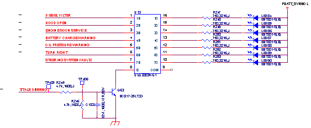
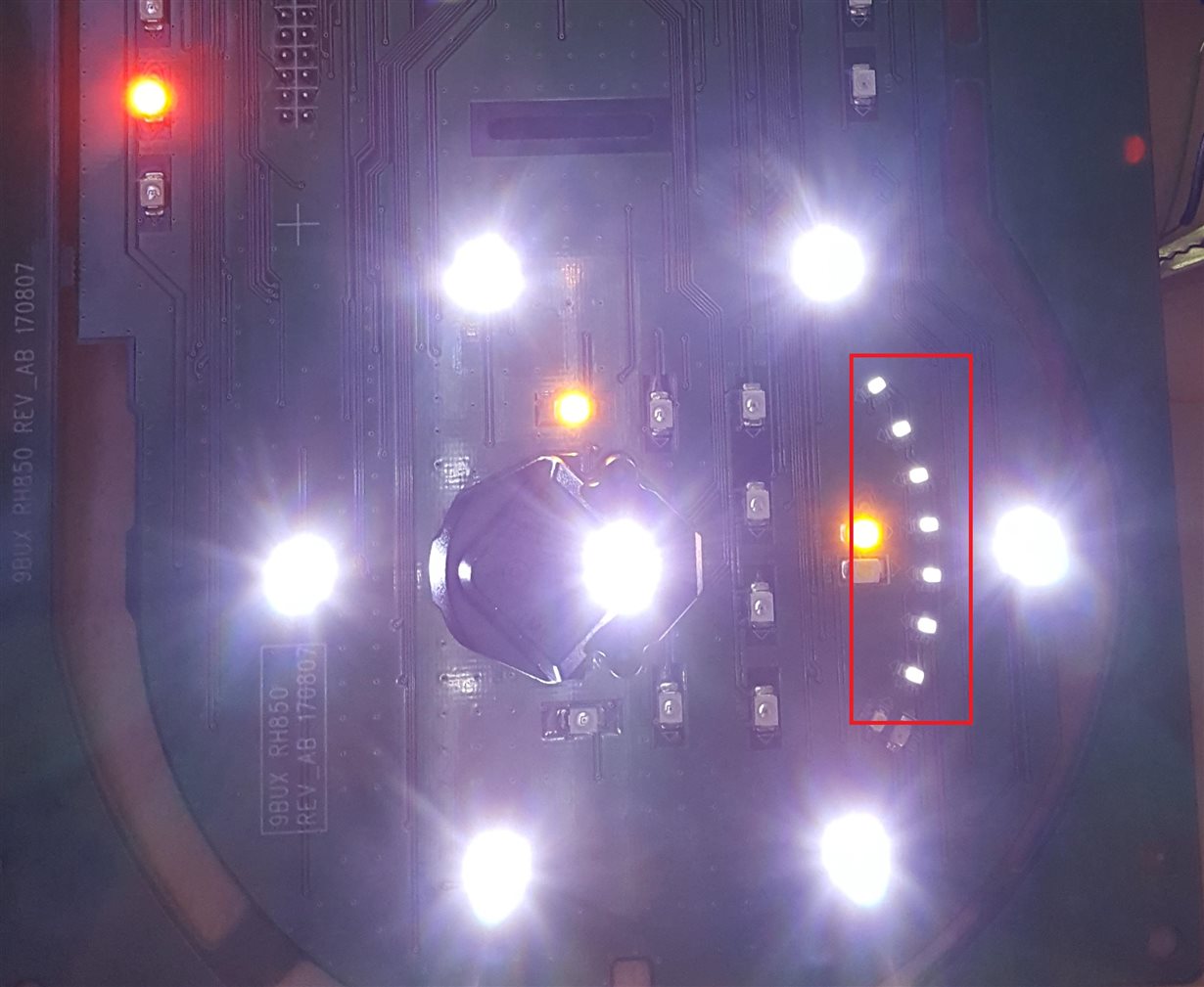
I recommended below schematic for dimming function but there is issue on this concept. Please refer to the below phenomenon and condition. I think 7 LEDs(RED box of below cluster picture) have to remain OFF status(currently half ON status) although changing Emitter signal because of no input signal.

Next week, the customer have to order PCB for approval working sample. This is urgent issue. I am sorry to bother you but please review and let me know your feedback ASAP. How can I solve this issue?

<Schematic concept>


<Abnormal phenomenon>

  • There is no input signal of ULQ2003A-Q1(1B~7B : Low) but LED output in ON(red box, half ON not fully ON)


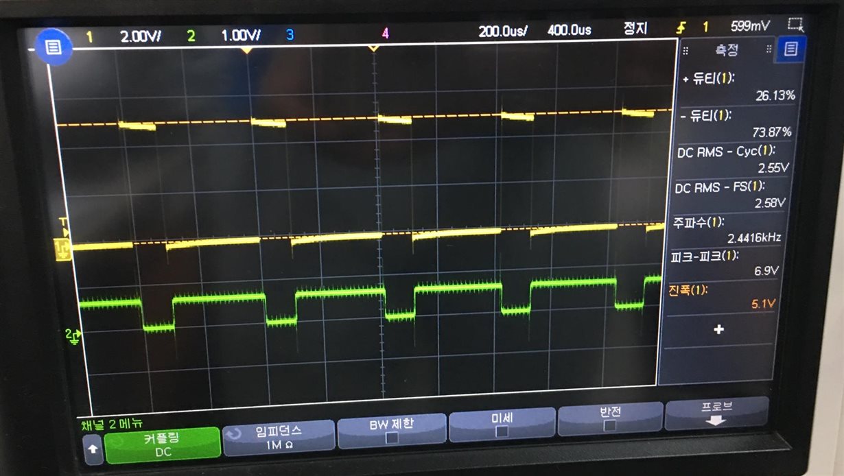
<Condition>

  • There is no input signal of ULQ2003A-Q1(1B~7B : Low)

  • Yellow signal : MCU dimming signal

  • Green signal : Port8 (E, emitter signal)


If you need more information, please let me know.

Thank you.

  • Hi Dino, 

    I'm a little confused on the functionality of the design. Are you trying to dim all of the 7 LEDs at the same time, or be able to turn on/off each LED individually? 

    With the current configuration with PWM on the emitter, it would be difficult to change each LED channel individually. It would be easier to control the dimming using 1B-7B instead. 

    In most of the examples using the ULQ2003A-Q1, the emitter is always connected to ground. When the emitter is connected to a PWM signal, this can cause current to flow back through the 7.2kΩ and 3kΩ resistors, biasing the BJT and allowing the LEDs to dim.

    Some further clarification would be appreciated!

    Thanks,

    Arthur Huang

  • Hello Arthur,

    Thank you for your comment.
    This application is able to turn on/off each LED individually. the reason using PWM on the emitter of ULQ2003A-Q1 is that there are many LED to control same dimming ratio not only ULQ2003A-Q1 but also discrete solution(only BJT control).
    You mentioned When the emitter is connected to a PWM signal, this can cause current to flow back through the 7.2kΩ and 3kΩ resistors, biasing the BJT and allowing the LEDs to dim. 

    Is there any solution to solve this issue using HW schematic change like adding resister or something? Please let me know your knowhow.

    Again Thank you.