This thread has been locked.

If you have a related question, please click the "Ask a related question" button in the top right corner. The newly created question will be automatically linked to this question.

UCC5320: how to use UCC5320 to drive SiC ?

Part Number: UCC5320

I am wondering any design tips for UCC5320 drive SiC ? appreciate your comments for this topic.

  • When driving SiC MOSFETs, the negative voltage bias and miller clamp are preferred. The reasons are:

    When SiC MOSFET is switching off, the current drawn by Miller capacitor causes a relatively high voltage drop on internal & external gate resistance, which induces voltage spike. If the voltage spike is higher than MOSFET threshold voltage, false trigger happens. SiC MOSFET generally has a lower threshold voltage and higher dV/dt than Si IGBT, so active miller clamp is preferred for SiC MOSFET.

    Negative voltage bias can also help keep the gate voltage below threshold voltage in off state.

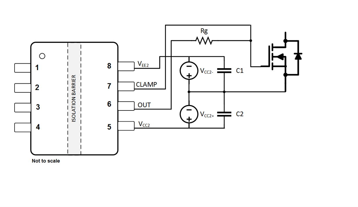
    In UCC53x0 family, UCC5310M could be a better choice than UCC5320E if using SiC MOSFET at high dV/dt switching. UCC5310M also supports negative voltage bias, although it does not have the GND pin. The negative voltage bias can be created as shown in the picture below.

    If using UCC5320E, external active miller clamp circuit is needed on board, which is costly and needs extra board space.

    Note: UCC5310M clamp threshold voltage uses a reference to VEE, if negative voltage bias is -4V, then the active clamp will be triggered at -4V+ Vclamp_th = -1.9V during off state.