This thread has been locked.

If you have a related question, please click the "Ask a related question" button in the top right corner. The newly created question will be automatically linked to this question.

SN65HVD73: fail safe circuit

Part Number: SN65HVD73

Hi

I have some question regarding the external fail safe circuit.

Do we need the external fail-safe circuit for the differential input when it is in the communication stop and line open?

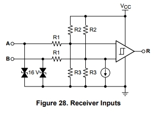
And how much the internal resistor(R1, R2 and R3) at the following block diagram? 

Regards,

Koji Hamamoto

  • Hi Koji,

    thanks for reaching out! This is a very common question, please take a look here:

    https://e2e.ti.com/support/interface/industrial_interface/f/142/p/640404/2362531#2362531

    but in a nutshell -There is no need for external biasing the SN65HVD73 has a internal fail circuit.

    K.Hamamoto said:
    And how much the internal resistor(R1, R2 and R3) at the following block diagram? 

    I can't find any block diagram, could you please post it again.

    Let me know is this is helping you out, don't hesitate to ask further questions!

    Kind regards 

    Dierk

  • Hi Dierk,

    Thank you for your support.

    I am sorry.Here is the block diagram what I asked. (How much is the R1 and R2, R3?)

    And I understood about the fail-safe circuit. (I found the function table of SN65HVD73. ; table 2. It is mentioned about fail safe function.)

    I appreciate your kind explanation.

    Regards,

    Koji Hamamoto

    Regards,

    Koji Hamamoto

  • Hi Koji,

    these three resistors have two tasks.

    The first is they have to divide Vcc from 3.3 V to a voltage range of estimated 1.9 V in order to provide the internal transistors gates of the amplifier stage headroom (below a certain level the transistor cuts off).

    The second is, the wide input range requires a attenuation of the input signal. lets assume factor 10.

    If all this is considered the estimated values are: R1 = 175 kOhm, R2 = 15.6 kOhm and R3 = 21.2 kOhm

    Kind regards

    Dierks

  • Hi Dierks,

    Thank you for your kind support.

    Please let me know how did you calculate the R1. (I understood about R2 and R3.)


    Regards,

    Koji Hamamoto

  • Hi Koji,

    from an AC perspective the resistor network can be viewed as R2 and R3 in parallel representing a voltage divider with R1 which provides the high input impedance and the attenuation for a wide common mode operation range.

    Kind regards

    Dierk