This thread has been locked.

If you have a related question, please click the "Ask a related question" button in the top right corner. The newly created question will be automatically linked to this question.

UCC21520: Voltage and current ringing during turn on and off

Part Number: UCC21520

Hello,

for a typical halfbridge application. Maximum Gate charge for my MOSFETs is 45nC.  Its blocking voltage is 600V. Max. . After calculation and considering in voltage ripple  Bootstrap cap value come up with 800nF. i have decided to choose 1uF cap for this application. I have performed double pulse test just to observe switching behavior of MOSFETs. 

Questions:

1- I have chosen 18 ohm turn on resistance and 9 ohm for turn off.

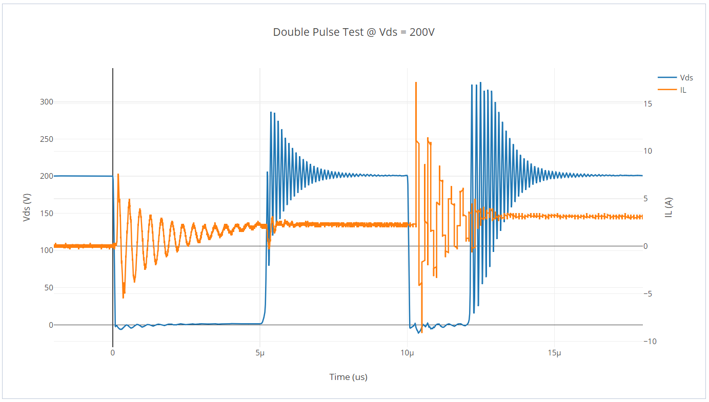
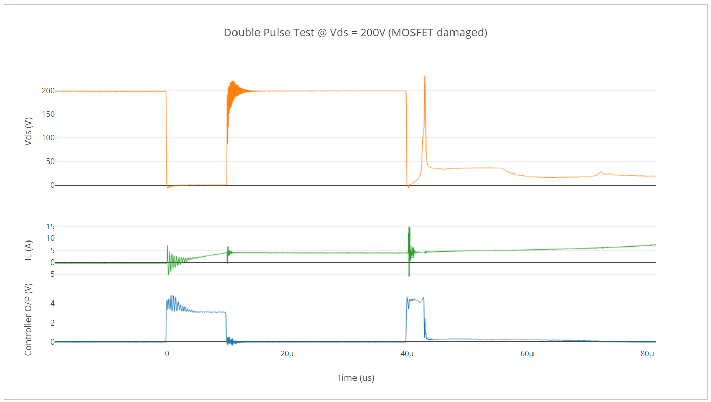
During measurements there is voltage ringing during turn off and current ringing during turn on which is almost 1.5 times of drain to source voltage. i have still available gate to source resistor and capacitor options available. what values of these capacitor and resistor should be to reduce ringing.  (R2 R3, C3 C4)

 kindly have look in figers.

here is double pulse result  for Vds = 200V.

  • Hello Muhammad, an engineer has been assigned to this thread and should reply soon.
  • Okay, I am waiting !
  • Hello Muhammad,

    Thanks for your interest in UCC21520. I see that you are using 600V FETs, but testing them at 200V. This is usually the worst case ringing for these FETs, because of the nonlinear C_oss behavior. Since the ringing is a function of the slew rate on the switch node and the FET parasitics, there is not much that can be done to reduce this ringing while maintaining the same slew rate. Increasing the gate resistor or increasing C3 and C4 would slow down the slew rate and minimize ringing, though this may be at an unacceptable cost to system performance. An R-C snubber on the switch node may also be able to help to some extent, but this method may not be successful if the bus voltage is varying since the capacitor value determining the ringing is also changing.

    If operation at fixed 200V is needed, I recommend selecting a transistor that is optimized for this voltage range.

    What is your expected bus voltage?

    Regards,
  • I have used IPP65R095C7 which has blocking voltage of 600V. DC link voltage is 400Vdc maximum. Let me be clear i was doing double pulse test by increasing Voltage step by step. I have inductor value 440mH. at 200 V my mosfet got dameged.

    Turn on R=18 and turn off =9 ohm, R2 and R3 is 1K and C3 C4 is 1n.

    kindly find attached results when MOSFETs got damaged !

  • Muhammad,

    Some of our internal tests have used C7 series MOSFETs in a half-bridge double pulse test in the past, and we sometimes saw issues where the MOSFET would be damaged in a similar way. We ultimately traced this back to the body diode dv/dt and di/dt limits, and based on your waveforms the di/dt at 200V bus voltage is likely much higher than this MOSFET can take. If you look through the Infineon product selection guides, you will find that C7 series MOSFETs are usually recommended for PFC applications where no body diode commutation is ever required. Double pulse tests at 200V are essentially the worst case usage for a C7 series MOSFET purely because of the way they are constructed, and there is not much that can be done from the driver side to mitigate this.

    If you are planning to use the body diode for commutation, C7 series MOSFETs are probably not the best choice. You will have better luck with C6 or CFD2 series which offer similar on-state resistances and more robust body diodes.

    Regards,
  • Thanks alot for your answer.

    In simple half bridge inverter application, can these C7 mosfets are okay to provide 2 Kw of power. Like i designed my Half bridge to provide KW of power?

    Can these MOSFETs operate without causing any damage, because for my application maximum current through them is 6 amp, and yes 230 of out put voltage while having DC link voltage 400Vdc ?

    If that so i can skip double pulse and go on with inverter normal testing using same DRIVER IC from Texas Instruments?
  • Muhammad,

    I don't know if you can use C7 MOSFETs in this application. An Infineon representative might be able to help you understand the MOSFET selection criteria in more detail. But if you have any additional questions about using the UCC21520, I can help with those.

    If your inverter design ever runs current through the body diode of your MOSFETs, you should try the double pulse test at the minimum DC link voltage for your application.

    Regards,