This thread has been locked.

If you have a related question, please click the "Ask a related question" button in the top right corner. The newly created question will be automatically linked to this question.

Question of UCC21520

Other Parts Discussed in Thread: UCC21520

I have questions about UCC21520.

Attachment is figure of digital isolator.

Does UCC21520 have the same structure?

Please tell us the internal suructure of Reinforced Isolation between primary and secondary.

Please tell us the Creepage distance.

Is the coupling capacitor between the primary side and the secondary side in the device double insolated?

Best regards,

Takahiro Nishizawa

Figure.pdf

  • Hello Nishizawa-san,

    UCC21520 has a similar structure to the digital isolator in the attachment, however some of the dimensions are different.

    The internal isolation is capacitive, and double-insulated, with one coupling capacitor present on each die.

    Since both the primary and the secondary are encased in insulating mold compound, it does not make sense to describe an internal creepage distance. The external creepage distance, per the insulation ratings table in the datasheet section 6.6, is at least 8 mm.

    Regards,
  • Thank you for your answer!


    Can you tell us the method of Reinforced Isolation?
    We want to know if it is insulated on the front side and back side of chip.


    Best regards,


    Takahiro Nishizawa
  • Hello Nishizawa-san,

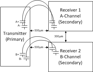
    UCC21520 reinforced isolation is created by internally coupling the input transmitter die (pins 1-8) to each of the two output receiver dice (pins 9-11 and 14-16) through two series capacitors. These capacitors are constructed using a nominal 10.5µm layer of SiO2 dielectric, with one capacitor built on the input transmitter die and one capacitor built on each of the output receiver dice. The bottom plates of the capacitors are connected to the transmitter and receiver, and the top plates are connected to each other with a bondwire. This construction is considered reinforced isolation because if one capacitor fails on the transmitter or the receiver, the other capacitor in series will maintain basic isolation from input to output.

    The two output receiver dice (pins 9-11 and 14-16) are functionally isolated from each other. The limiting factor is the creepage distance between pin 11 and pin 14.

    Please let me know if this answers your question.

    Regards,

  • Thank you for your answer!

    Our customer wants you to show the figure about construction of IC.
    They want to check the figure such as attached document in this e2e mail of Jun 19, 2018 10:28 PM.
    Is it possible to illustrate your answer?


    Best regards,


    Takahiro Nishizawa
  • Hello Nishizawa-san,

    What specific information on the diagram are they looking for? Some information is only available if we have an NDA with this customer (such as internal leadframe dimensions and clearances). If we have an NDA with this customer, I can provide leadframe information in a private message.

    I can confirm that the diagram in the attached document is a simplified, but accurate, representation of the construction of UCC21520DW.

    Regards,

  • Thank you for your answer!


    About attached document(Jun 19, 2018 10:28 PM e2e),
    Please tell us the difference between UCC21520 and Attached document(digital isolator).

    Best regards,


    Takahiro Nishizawa
  • Hello Nishizawa-san,

    The isolation technology, layer stackup, and 500µm dimension between the transmitter and receiver leadframe are the same. The difference is that in your attached document (Jun 19), there is only one receiver die. In UCC21520, there are two separate receivers, with 300µm between the receiver leadframes as well.

    I also said that the drawing was simplified. In both UCC21520 and the digital isolator, the signal is transmitted differentially across the isolation barrier to improve noise rejection.

    Please see the image below.

    Regards,