This thread has been locked.

If you have a related question, please click the "Ask a related question" button in the top right corner. The newly created question will be automatically linked to this question.

SN65HVD230: CAN Physical interface problem

Part Number: SN65HVD230

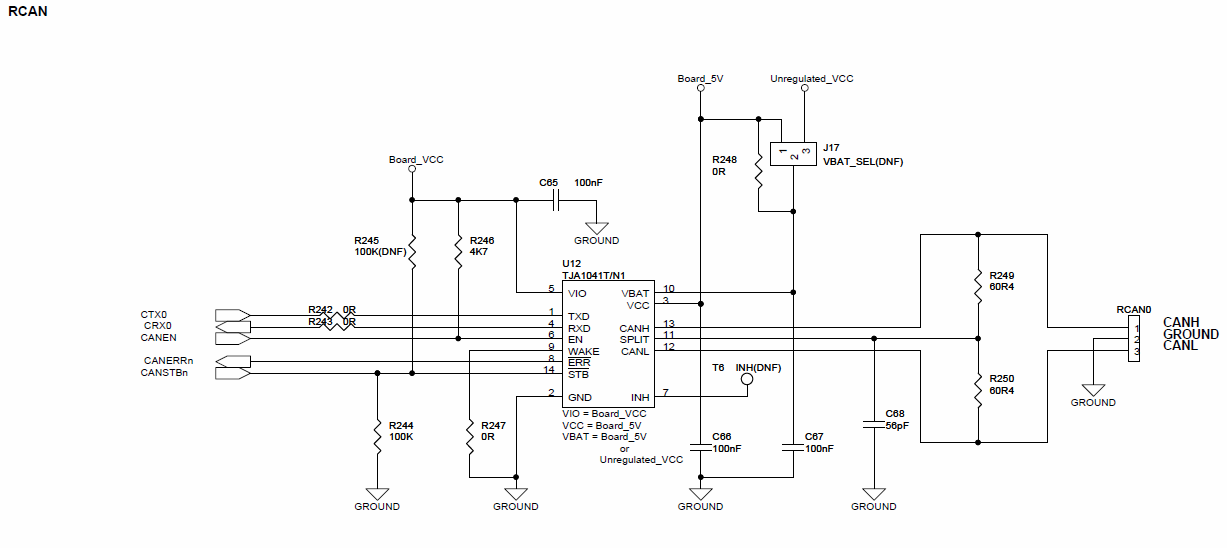
HI! I've started working with a board already developed and needed to implement CAN protocol on a non-TI MCU. I've tested first an internal loop to get the libraries working and then, when I tried to output and transmit on CANP and CANH differential signals, I couldn't get anything. So I started testing the modules. Here's the schematic implemented:

Schematic

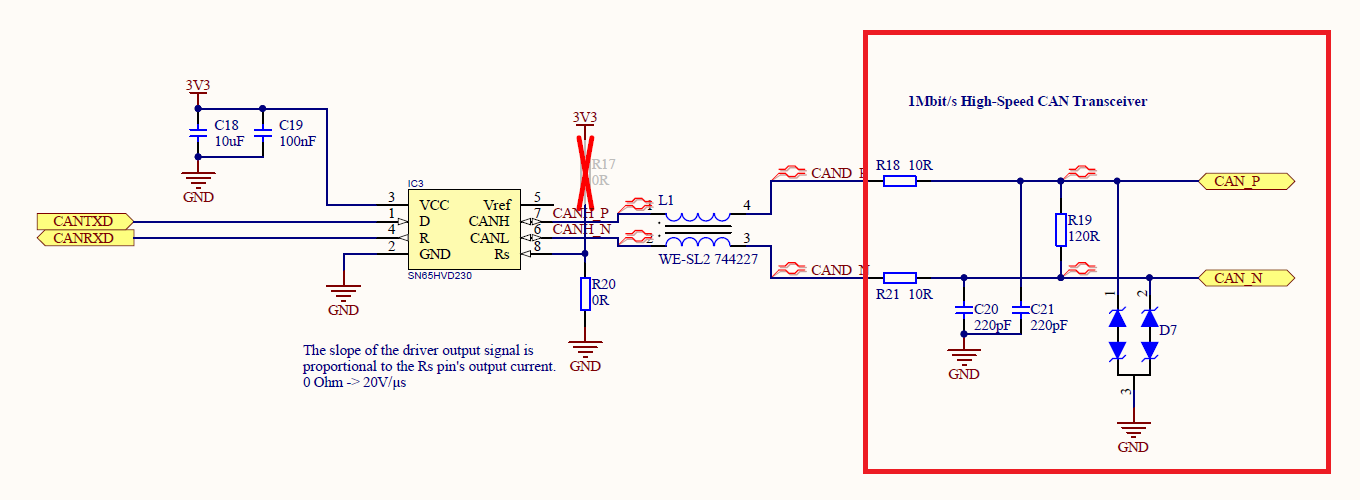
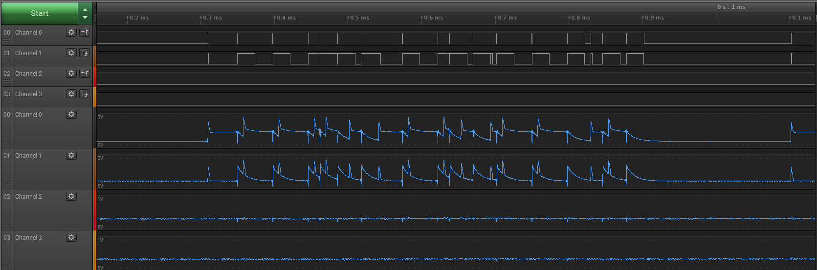
I measured CANTXD and CANRXD signals outside the microcontroller, and are correct, and are getting correctly to pins 1 and 4 of the SN65HVD230:

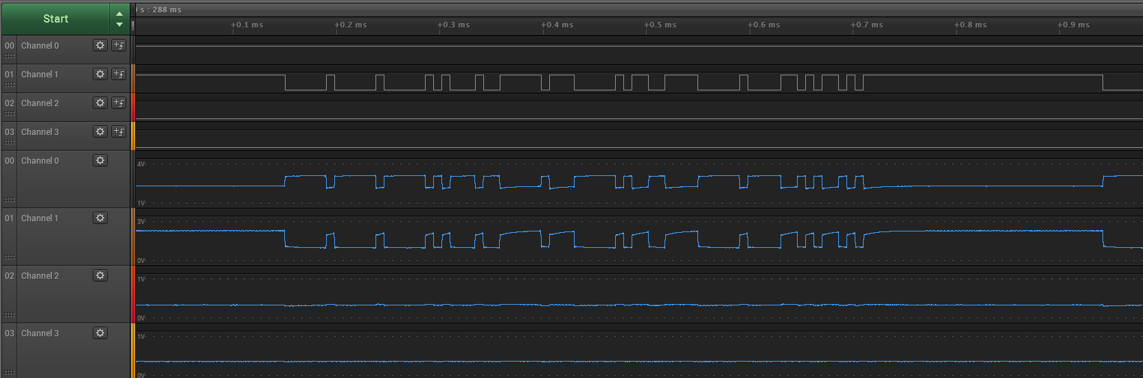
Then I measured the device's differential output at pins 6 and 7 and this is what I got:

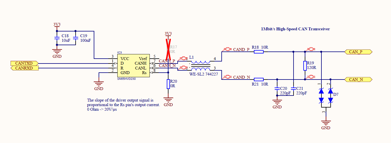
I measured the Common Mode Line Filter's output too, but still, SN65HVD230's output doesn't seem right to me. I would appreciate any tips or ideas regarding what to check here, so I can keep testing this module. 

Thanks!

  • Hi Franco,

    It looks like there's a lot of capacitance on the CAN bus which is causing the spikes you see in the second figure. You may want to lower the bus filter capacitance (C20 and C21) to be in the 20pF to 60pF range. This could also be caused by other device on the bus that effects the capacitance or is fighting what the device is driving. What else is connected to the bus in this test?

    Also what do Channels 0 and 1 represent in the second figure? Are these TxD and RxD?

    Regards,
    Eric
  • Hi Erik,

    thanks for the reply. I'll see what I can do about C20 and C21.

    To answer your questions, the only device connected to the bus is a development board, directly connected to this custom board. This is the setup:

    In Figure 2, Channel 1 is TxD and Channel 2 is RxD. In my previous tests running only CAN bus on the development board, I got the same results, even though it wasn't connected to any other devices. What I mean is that RxD was exactly the same as TxD although no other device was transmitting, since there was no other device connected.

    Anyways, I still don't have any signal after R18 and R21, and doesn't matter if anything is connected to the bus, since signals don't reach CAN_P and CAN_N pins:

    Regards,
    Franco

  • As an update, I found that when one of the modules (one with an Ethernet connector and two CAN connectors) is attached to the circuit  through a terminal strip, then every signal is connected to ground. Here are CAN_P and CAN_H signals after detaching the module:

    I belibeve then, that this is my problem.

    Thanks for the help!

    Regards,

    Franco

  • Hi Franco,

    I'm glad you were able to find a solution to the problem. Best of luck on the rest of the project!

    Regards,
    Eric