This thread has been locked.

If you have a related question, please click the "Ask a related question" button in the top right corner. The newly created question will be automatically linked to this question.

TPL7407L: TPL7407L unexpectedly failing driving brushed DC motor.

Part Number: TPL7407L

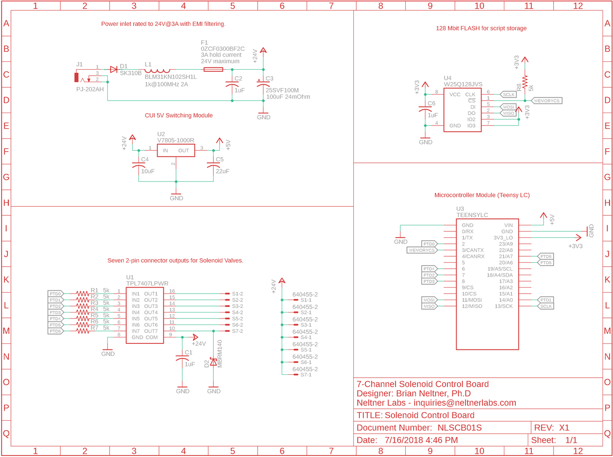
I have a simple implementation for the TPL7407L intended for a solenoid driver, shown below. The Teensy LC is a basic microcontroller module and there is 128MBit of flash but otherwise the design was intended to be basically a direct copy of the datasheet plus the input power filtering and fuse.

I mostly intended this for use with solenoids in the 50mA range, but since the chip is rated for it I wanted to prove it would work with a brushed motor that draws about 200mA. Well within the current, only one channel on at a time.

So I plugged it all in using a 14V battery for V+ (i.e. +24V on the schematic is actually +14V) and connected to the motor. It worked a little but had *that* smell. Next time trying to turn it on the chip seems to be fried and the motor is just full on all the time. Resistance on that channel's OUT1 to GND is ~1 ohm and all the other channels similarly appear to have blown up.

Could someone from TI or an expert in the community explain? I see nothing in the datasheet that I wasn't careful to do, but my colleague said it was necessary to add a zener diode on V+ of ~30V or so to ensure that the voltage to the board doesn't spike and blow up the common. This is all still a bit out of my expertise area so I'd love to hear any second opinions. I thought the driver had everything needed to handle inductive loads already, do I need to also add an undocumented zener in the same place as C1 to keep the TPL7407 from blowing up? I'm quite confused.

Or maybe these particular brushed motors have a higher inrush current somehow than we measured? I didn't do that part, so they may. Should I be doing something like throwing a choke on the OUT1/OUT2 lines to prevent current spikes?

  • Looks like my attached image of the schematic didn't take, I'll try again here:

    Solenoid Valve Control Board.pdf

  • Hi Brian,

    You are correct that these devices already have a flyback diode integrated, and the way you have connected your device looks to be appropriate. However, the abs max ratings of the device would still need to be considered when turning on/off these loads. Would you be able to capture a scope shot of the turn on/off even that damages the device? This would be the voltage waveform on OUT and COM.

    One thing you could try would be adding a resistance between your supply and the COM pin, as this will limit the transient current during switching. The diode may also work if the problem is the COM pin swinging too high.

    I think the waveforms would be pretty telling since we could see exactly what the device is seeing before damage.

    Thanks,

    Alek Kaknevicius

  • Hi Alek,

    Interesting approach. I can't promise I'll get around to destructively testing my prototype to figure out why the TPL7407L is breaking. It's probably a reasonable approach but I just don't have time for that and won't for a few months. And the pumps are offsite, and they don't even have an oscilloscope.

    How much current flows into or out of the COM pin? A resistor there sounds like a good idea, but I'm assuming it can't be a very big resistor right?

  • Hi Brian,

    The COM pin only needs 30uA max to properly function, so adding the resistor shouldn't limit device operation. The benefit of adding it is to limit the current through the flyback diode when switching on/off the load. It's hard to say what exactly is getting damaged on the IC since the schematic does not look problematic, but the above may help if the damage is on the flyback diode from each output to COM.

    Thanks,

    Alek Kaknevicius

  • Thanks Alek, I'll just add both a 10k and a 30V zener diode on the COM pin then. I agree that I can't think of much else that could be causing it.

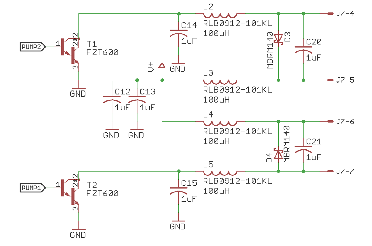
    If I were doing this by hand I'd probably put an inductor on both the supply and return lines to the motor as well as a capacitor and schottky diode between the motor leads to discharge current, and possibly capacitors to ground between the top of the BJT and ground to form a pi network.

    How much of that is definitely redundant with the TPL7407L?

    This is how I would do it with a BJT (I'm not a power electronics engineer, this may be a terrible circuit) --