This thread has been locked.

If you have a related question, please click the "Ask a related question" button in the top right corner. The newly created question will be automatically linked to this question.

TL16C752C: Not able to get RX data out of device, always returns zeros

Part Number: TL16C752C

Hello TI  team,

TL16C752C DUART A has been mapped with C6711 DSP and DUART chip has been configured for 38400 baud rate, 1 stop bit, parity as None. It has also been configured in FIFO mode. I am transmitting some dummy data from PC to test the communication. LSR register is updating that DUART has received some data in its Rx Buffer but RHR register is always providing the data as 0 (decimal).

We have tracked Chip select pin for UART A with oscilloscope also and it is working fine.

Another update is that - This is the legacy system and previously we were using TL16C752B part and code is working well for this part.

Please update at the earliest.

Regards,

  • Hi Tom,

    We'll get back to you shortly. Our expert on this part is getting back from vacation tomorrow and should be able to help guide you in the right direction. Sorry for the delay.

    Max
  • We have not heard from anyone on this posting.. We are in a holding pattern with this issues. We cannot continue integration without this DUART functional. Can we get Support!!!!!
  • Hello Tom

    Sorry for my delay. Can you share mode details regarding your configuration? It looks like you have an overflow but if this one doesn't happen in version B, I would like to know more details like: Vcc, clock frequency, amplitude.
    The B version works up to 3.3 V but the version C and D work up to 5 V.

    Please, let me know this information.

    Regards
    Francisco
  • My FW engineer stepped out I am the EE. We are using +3.3V at it is ok at the part. I have an external crystal this is at a stable 14.7456MHz.

    We are using a PC to send TX data into the Device. I have a test wire at pin 5 and see our data there. When the SW engineer sees the LSR Register, LSR register provides value as 0x61 which updates that data is present in Rx FIFO and there is no any parity, overflow and framing error. When he reads the RHR register it provides only 0's... He sent in nine bytes and he detected 9 bits received each time the register indicated data was there.

    Data can be transmitted out of the DUART when it comes from the Parallel port side of the DUART.. so we believe that side of the DUART is functioning.

    We are working with channel A and B, channel A we use to program the DSP and channel B is interfaced with Bluetooth module.

    We have an external Reset signal at pin 36. It is stable and is produced by a supervisor chip.

    I believe my FW engineer looked at the posted errata, and believes this errata is not causing this problem.

    We previously used TL16C752B with no problems..
  • Tom thanks for your feedback.

    I can to understand that the CHA and CHB are working like receiver and both UARTs are programed as the same way.
    So please, Can you please explain how you program the baud rate?
    Can you confirm if the registers DLL and DLH have the value that you programed before and after the communication?
    Can you confirm if the reset pin is in low level?
    Can you please add an extra reset before of the communication?
    Can you send the value of the LCR register?
    Which is the value of the prescaler?
    Do you have this device in a socket?

    I asked these questions to understand better the issue and give you the best recommendation.

    Regards
    Francisco
  • Dear Francisco,

    From Tom...

    The IC is soldered to the board. The reset applied to the part is from a supervsior IC. Once power is good the reset is deasserted.
    We cannot apply a second reset without cycling power. The reset is active high

    I have included the Baud Rate function

    Prescaler value is 1.

    I will confirm the values of DLL, DLH and LCR registers later and update you.

    Regards,
    Anuj


    How can we attach files to the posting?


    Bool UART_SetBaud( UART_PORT Port,
    UART_BAUD Baud )
    {
    Uint8 byVal;
    Uint8 byDivisorL;
    Uint8 byDivisorH;
    Uint8 *pDuart;

    // Select the port
    switch( Port )
    {
    case UART_A:
    pDuart = gv_pDuartA;
    break;

    case UART_B:
    pDuart = gv_pDuartB;
    break;

    default:
    return FALSE;
    }


    //////////////////////////////////////////////
    // Set the divisors for the proper baud rate

    switch( Baud )
    {
    case UART_B300:
    byDivisorH = 0x0C;
    byDivisorL = 0x00;
    break;

    case UART_B600:
    byDivisorH = 0x06;
    byDivisorL = 0x00;
    break;

    case UART_B1200:
    byDivisorH = 0x03;
    byDivisorL = 0x00;
    break;

    case UART_B2400:
    byDivisorH = 0x01;
    byDivisorL = 0x80;
    break;

    case UART_B4800:
    byDivisorH = 0x00;
    byDivisorL = 0xC0;
    break;

    case UART_B9600:
    byDivisorH = 0x00;
    byDivisorL = 0x60;
    break;

    case UART_B19200:
    byDivisorH = 0x00;
    byDivisorL = 0x30;
    break;

    case UART_B38400:
    byDivisorH = 0x00;
    byDivisorL = 0x18;
    break;

    case UART_B56000:
    byDivisorH = 0x00;
    byDivisorL = 0x10;
    break;

    case UART_B115200:
    byDivisorH = 0x00;
    byDivisorL = 0x08;
    break;

    default:
    return FALSE;
    }

    // Access the clock rate divisor
    byVal = pDuart[DUART_LCR];
    pDuart[DUART_LCR] = 0x80;

    // Set the divisor
    pDuart[DUART_DLL] = byDivisorL;
    pDuart[DUART_DLH] = byDivisorH;

    // Go back to normal operation
    pDuart[DUART_LCR] = byVal & ~0x80;

    // Good operation
    return TRUE;
    } // end UART_SetBaud
  • Hello Tom

    You can attach something using the part "Use rich formatting" I would like to see a diagram of your connection. Can you also attach the order that you are programing the UART? as you said with 0x80 in LCR you have 5 bits transmitted or received, Are these quantity of bits that you are sent from PC to UART? you are using 1 stop bit, no parity.
    Please, attach the files and I'll check it out.

    Regards
    Francisco
  • UART.c
    #include <stdio.h>
    #include <std.h>
    #include <csl.h>
    
    #include "UART.h"
    
    // Point to each DUART port's set of registers
    static Uint8	*gv_pDuartA = (Uint8 *)DUARTA_BASE;
    static Uint8	*gv_pDuartB = (Uint8 *)DUARTB_BASE;
    
    
    //////////////////////////////////////////////////////////////////////////////
    // Function:	UART_SetBaud
    //
    // Description:	Sets the baud rate for the given port.
    //
    // Parameters:	Port [in] - The UART port to use
    //					UART_A
    //					UART_B
    //				Baud [in] - The baud rate to use
    //					UART_B300
    //					UART_B600
    //					UART_B1200
    //					UART_B2400
    //					UART_B4800
    //					UART_B9600
    //					UART_B19200
    //					UART_B38400
    //					UART_B56000
    //
    // Returns:		TRUE - Successful
    //				FALSE - Not successful
    //
    // Caveats:		None
    //
    // Maintenance:
    // 11-11-03 RDM	Updated for new 14.7456MHz crystal.
    // 09-12-03 RDM	Now using gv_pDuartA & gv_pDuartB for DUART register access.
    // 07-25-03 RDM	Genesis
    //////////////////////////////////////////////////////////////////////////////
    
    Bool UART_SetBaud( UART_PORT Port, 
                       UART_BAUD Baud )
    {
    	Uint8	byVal;
    	Uint8	byDivisorL;
    	Uint8	byDivisorH;
    	Uint8	*pDuart;
    
    	// Select the port
    	switch( Port )
    	{
    	case UART_A:
    		pDuart = gv_pDuartA;
    		break;
    
    	case UART_B:
    		pDuart = gv_pDuartB;
    		break;
    
    	default:
    		return FALSE;
    	}
    
    
    	//////////////////////////////////////////////
    	// Set the divisors for the proper baud rate
    
    	switch( Baud )
    	{
    	case UART_B300:
    		byDivisorH = 0x0C;
    		byDivisorL = 0x00;
    		break;
    
    	case UART_B600:
    		byDivisorH = 0x06;
    		byDivisorL = 0x00;
    		break;
    
    	case UART_B1200:
    		byDivisorH = 0x03;
    		byDivisorL = 0x00;
    		break;
    
    	case UART_B2400:
    		byDivisorH = 0x01;
    		byDivisorL = 0x80;
    		break;
    
    	case UART_B4800:
    		byDivisorH = 0x00;
    		byDivisorL = 0xC0;
    		break;
    
    	case UART_B9600:
    		byDivisorH = 0x00;
    		byDivisorL = 0x60;
    		break;
    
    	case UART_B19200:
    		byDivisorH = 0x00;
    		byDivisorL = 0x30;
    		break;
    
    	case UART_B38400:
    		byDivisorH = 0x00;
    		byDivisorL = 0x18;
    		break;
    
    	case UART_B56000:
    		byDivisorH = 0x00;
    		byDivisorL = 0x10;
    		break;
    
    	default:
    		return FALSE;
    	}
    
    	// Access the clock rate divisor
    	byVal = pDuart[DUART_LCR];
    	pDuart[DUART_LCR] = 0x80;	
    
    	// Set the divisor
    	pDuart[DUART_DLL] = byDivisorL;
    	pDuart[DUART_DLH] = byDivisorH;
    	
    	// Go back to normal operation
    	pDuart[DUART_LCR] = byVal & ~0x80;
    
    	// Good operation
    	return TRUE;
    } // end UART_SetBaud
    
    
    //////////////////////////////////////////////////////////////////////////////
    // Function:	UART_SetParity
    //
    // Description:	Sets the parity for the given port.
    //
    // Parameters:	Port [in] - The UART port to use
    //					UART_A
    //					UART_B
    //				Parity [in] - The parity to set
    //					UART_PARITY_NONE
    //					UART_PARITY_ODD
    //					UART_PARITY_EVEN
    //					UART_PARITY_MARK
    //					UART_PARITY_SPACE
    //
    // Returns:		TRUE - Successful
    //				FLASE - Not successful
    //
    // Caveats:		None
    //
    // Maintenance:
    // 09-12-03 RDM	Now using gv_pDuartA & gv_pDuartB for DUART register access.
    // 07-25-03 RDM	Genesis
    //////////////////////////////////////////////////////////////////////////////
    
    Bool UART_SetParity( UART_PORT Port, 
                         UART_PARITY Parity )
    {
    	Uint8	byVal;
    	Uint8	byMask;
    	Uint8	*pDuart;
    	
    	
    	////////////////////
    	// Select the port
    
    	switch( Port )
    	{
    	case UART_A:
    		pDuart = gv_pDuartA;
    		break;
    
    	case UART_B:
    		pDuart = gv_pDuartB;
    		break;
    
    	default:
    		return FALSE;
    	}
    
    
    	////////////////////////////////
    	// Set the mask for the parity
    
    	switch( Parity )
    	{
    	case UART_PARITY_NONE:
    		byMask = NONE_MASK;
    		break;
    
    	case UART_PARITY_ODD:
    		byMask = ODD_MASK;
    		break;
    
    	case UART_PARITY_EVEN:
    		byMask = EVEN_MASK;
    		break;
    
    	case UART_PARITY_MARK:
    		byMask = MARK_MASK;
    		break;
    
    	case UART_PARITY_SPACE:
    		byMask = SPACE_MASK;
    		break;
    
    	default:
    		return FALSE;
    	}
    
    	// Get the initial line-control value
    	byVal = pDuart[DUART_LCR];
    	
    	// Clear the parity bits
    	byVal &= PARITY_MASK;
    	
    	// Set the requested parity
    	byVal |= byMask;
    	
    	// Set the new parity
    	pDuart[DUART_LCR] = byVal;
    
    	// Good operation
    	return TRUE;
    } // end UART_SetParity
    
    
    //////////////////////////////////////////////////////////////////////////////
    // Function:	UART_SetDataLength
    //
    // Description:	Sets the number of data bits for the given port.
    //
    // Parameters:	Port [in] - The UART port to use
    //					UART_A
    //					UART_B
    //				DataBits [in] - The number of data bits to set
    //					UART_DATA_BITS_5
    //					UART_DATA_BITS_6
    //					UART_DATA_BITS_7
    //					UART_DATA_BITS_8
    //
    // Returns:		TRUE - Successful
    //				FALSE - Not successful
    //
    // Caveats:		None
    //
    // Maintenance:
    // 09-12-03 RDM	Now using gv_pDuartA & gv_pDuartB for DUART register access.
    // 07-25-03 RDM	Genesis
    //////////////////////////////////////////////////////////////////////////////
    
    Bool UART_SetDataLength( UART_PORT Port, 
                             UART_DATA_BITS DataBits )
    {
    	Uint8	byVal;
    	Uint8	byMask;
    	Uint8	*pDuart;
    
    	////////////////////
    	// Select the port
    
    	switch( Port )
    	{
    	case UART_A:
    		pDuart = gv_pDuartA;
    		break;
    
    	case UART_B:
    		pDuart = gv_pDuartB;
    		break;
    
    	default:
    		return FALSE;
    	}
    
    
    	///////////////////////////////////
    	// Set the mask for the stop bits
    
    	switch( DataBits )
    	{
    	case UART_DATA_BITS_5:
    		byMask = DL5_MASK;
    		break;
    
    	case UART_DATA_BITS_6:
    		byMask = DL6_MASK;
    		break;
    
    	case UART_DATA_BITS_7:
    		byMask = DL7_MASK;
    		break;
    
    	case UART_DATA_BITS_8:
    		byMask = DL8_MASK;
    		break;
    
    	default:
    		return FALSE;
    	}
    
    
    	// Get the initial line-control value
    	byVal = pDuart[DUART_LCR];
    	
    	// Clear the data length bits
    	byVal &= DL_MASK;
    	
    	// Set the requested data length
    	byVal |= byMask;
    	
    	// Set the new value
    	pDuart[DUART_LCR] = byVal;
    
    	// Good operation
    	return TRUE;
    } // end UART_SetDataLength
    
    
    //////////////////////////////////////////////////////////////////////////////
    // Function:	UART_SetStopBits
    //
    // Description:	Sets the number of stop bits for the given port.
    //
    // Parameters:	Port [in] - The UART port to use
    //					UART_A
    //					UART_B
    //				StopBits [in] - The number of stop bits
    //					UART_STOP_BITS_1
    //					UART_STOP_BITS_1_5	(1.5 stop bits)
    //					UART_STOP_BITS_2
    //
    // Returns:		TRUE - Successful
    //				FALSE - Not successful
    //
    // Caveats:		None
    //
    // Maintenance:
    // 09-12-03 RDM	Now using gv_pDuartA & gv_pDuartB for DUART register access.
    // 07-25-03 RDM	Genesis
    //////////////////////////////////////////////////////////////////////////////
    
    Bool UART_SetStopBits( UART_PORT Port, 
                           UART_STOP_BITS StopBits )
    {
    	Uint8	byVal;
    	Uint8	byMask;
    	Uint8	*pDuart;
    	
    	
    	////////////////////
    	// Select the port
    
    	switch( Port )
    	{
    	case UART_A:
    		pDuart = gv_pDuartA;
    		break;
    
    	case UART_B:
    		pDuart = gv_pDuartB;
    		break;
    
    	default:
    		return FALSE;
    	}
    
    
    	///////////////////////////////////
    	// Set the mask for the stop bits
    
    	switch( StopBits )
    	{
    	case UART_STOP_BITS_1:
    		byMask = SB1_MASK;
    		break;
    
    	case UART_STOP_BITS_1_5:
    		byMask = SB1_5_MASK;
    		break;
    
    	case UART_STOP_BITS_2:
    		byMask = SB2_MASK;
    		break;
    
    	default:
    		return FALSE;
    	}
    
    	// Get the initial line-control value
    	byVal = pDuart[DUART_LCR];
    	
    	// Clear the stop bits
    	byVal &= STOP_MASK;
    	
    	// Set the requested stop bits
    	byVal |= byMask;
    	
    	// Set the new value
    	pDuart[DUART_LCR] = byVal;
    
    	// Good operation
    	return TRUE;
    } // end UART_SetStopBits
    
    
    //////////////////////////////////////////////////////////////////////////////
    // Function:	UART_SetDTR
    //
    // Description:	Sets the state of the DTR (data terminal ready) line.
    //
    // Parameters:	Port [in] - The UART port to use
    //					UART_A
    //					UART_B
    //				bState [in] - The state to set the line.
    //
    // Returns:		None
    //
    // Caveats:		None
    //
    // Maintenance:
    // 09-12-03 RDM	Now using gv_pDuartA & gv_pDuartB for DUART register access.
    // 07-25-03 RDM	Genesis
    //////////////////////////////////////////////////////////////////////////////
    
    void UART_SetDTR( UART_PORT Port, 
                      Bool bState )
    {
    	Uint8	byVal;
    	Uint8	*pDuart;
    
    	////////////////////
    	// Select the port
    
    	switch( Port )
    	{
    	case UART_A:
    		pDuart = gv_pDuartA;
    		break;
    
    	case UART_B:
    		pDuart = gv_pDuartB;
    		break;
    
    	default:
    		return;
    	}
    
    
    	// Set (or clear) the DTR line
    	byVal = pDuart[DUART_MCR];
    
    	if( bState == FALSE )
    	{
    		byVal &= ~UART_MCR_DTR_MASK;
    	}
    	else
    	{
    		byVal |= UART_MCR_DTR_MASK;
    	}
    	
    	pDuart[DUART_MCR] = byVal;
    } // end UART_SetDTR
    
    
    //////////////////////////////////////////////////////////////////////////////
    // Function:	UART_SetRTS
    //
    // Description:	Sets the state of the RTS (ready to send) line.
    //
    // Parameters:	Port [in] - The UART port to use
    //					UART_A
    //					UART_B
    //				bState [in] - The state to set the line.
    //
    // Returns:		None
    //
    // Caveats:		None
    //
    // Maintenance:
    // 09-12-03 RDM	Now using gv_pDuartA & gv_pDuartB for DUART register access.
    // 07-25-03 RDM	Genesis
    //////////////////////////////////////////////////////////////////////////////
    
    void UART_SetRTS( UART_PORT Port, 
                      Bool bState )
    {
    	Uint8	byVal;
    	Uint8	*pDuart;
    
    	////////////////////
    	// Select the port
    
    	switch( Port )
    	{
    	case UART_A:
    		pDuart = gv_pDuartA;
    		break;
    
    	case UART_B:
    		pDuart = gv_pDuartB;
    		break;
    
    	default:
    		return;
    	}
    
    	// Set (or clear) the RTS line
    	byVal = pDuart[DUART_MCR];
    	
    	if( bState == FALSE )
    	{
    		byVal &= ~UART_MCR_RTS_MASK;
    	}
    	else
    	{
    		byVal |= UART_MCR_RTS_MASK;
    	}
    	
    	pDuart[DUART_MCR] = byVal;
    } // end UART_SetRTS
    
    
    //////////////////////////////////////////////////////////////////////////////
    // Function:	UART_ReadCTS
    //
    // Description:	Reads the state of the CTS (clear to send) line.
    //
    // Parameters:	Port [in] - The UART port to use
    //					UART_A
    //					UART_B
    //
    // Returns:		TRUE - CTS active
    //				FALSE - CTS not active
    //
    // Caveats:		None
    //
    // Maintenance:
    // 09-12-03 RDM	Now using gv_pDuartA & gv_pDuartB for DUART register access.
    // 07-25-03 RDM	Genesis
    //////////////////////////////////////////////////////////////////////////////
    
    Bool UART_ReadCTS( UART_PORT Port )
    {
    	Uint8	byVal;
    	Uint8	*pDuart;
    
    	// Select the port
    	switch( Port )
    	{
    	case UART_A:
    		pDuart = gv_pDuartA;
    		break;
    
    	case UART_B:
    		pDuart = gv_pDuartB;
    		break;
    
    	default:
    		return;
    	}
    
    
    	// Read the status
    	byVal = pDuart[DUART_MSR];
    	
    	if( (byVal & CTS_MASK) == 0 )
    	{
    		return FALSE;
    	}
    	
    	return TRUE;
    } // end UART_ReadCTS
    
    
    //////////////////////////////////////////////////////////////////////////////
    // Function:	UART_ReadDSR
    //
    // Description:	Reads the state of the DSR (data set ready) line.
    //
    // Parameters:	Port [in] - The UART port to use
    //					UART_A
    //					UART_B
    //
    // Returns:		TRUE - DSR active
    //				FALSE - DSR not active
    //
    // Caveats:		None
    //
    // Maintenance:
    // 09-12-03 RDM	Now using gv_pDuartA & gv_pDuartB for DUART register access.
    // 07-25-03 RDM	Genesis
    //////////////////////////////////////////////////////////////////////////////
    
    Bool UART_ReadDSR( UART_PORT Port )
    {
    	Uint8	byVal;
    	Uint8	*pDuart;
    
    
    	////////////////////
    	// Select the port
    
    	switch( Port )
    	{
    	case UART_A:
    		pDuart = gv_pDuartA;
    		break;
    
    	case UART_B:
    		pDuart = gv_pDuartB;
    		break;
    
    	default:
    		return;
    	}
    
    
    	// Read the status
    	byVal = pDuart[DUART_MSR];
    	
    	if( (byVal & DSR_MASK) == 0 )
    	{
    		return FALSE;
    	}
    	
    	return TRUE;
    } // end UART_ReadDSR
    
    
    //////////////////////////////////////////////////////////////////////////////
    // Function:	UART_ReadRI
    //
    // Description:	Reads the state of the RI (ring indicator) line.
    //
    // Parameters:	Port [in] - The UART port to use
    //					UART_A
    //					UART_B
    //
    // Returns:		TRUE - RI active
    //				FALSE - RI not active
    //
    // Caveats:		None
    //
    // Maintenance:
    // 09-12-03 RDM	Now using gv_pDuartA & gv_pDuartB for DUART register access.
    // 07-25-03 RDM	Genesis
    //////////////////////////////////////////////////////////////////////////////
    
    Bool UART_ReadRI( UART_PORT Port )
    {
    	Uint8	byVal;
    	Uint8	*pDuart;
    
    
    	////////////////////
    	// Select the port
    
    	switch( Port )
    	{
    	case UART_A:
    		pDuart = gv_pDuartA;
    		break;
    
    	case UART_B:
    		pDuart = gv_pDuartB;
    		break;
    
    	default:
    		return;
    	}
    
    
    	// Read the status
    	byVal = pDuart[DUART_MSR];
    	
    	if( (byVal & RI_MASK) == 0 )
    	{
    		return FALSE;
    	}
    	
    	return TRUE;
    } // end UART_ReadRI
    
    
    //////////////////////////////////////////////////////////////////////////////
    // Function:	UART_ReadCD
    //
    // Description:	Reads the state of the CD (carrier detect) line.
    //
    // Parameters:	Port [in] - The UART port to use
    //					UART_A
    //					UART_B
    //
    // Returns:		TRUE - CD active
    //				FALSE - CD not active
    //
    // Caveats:		None
    //
    // Maintenance:
    // 09-12-03 RDM	Now using gv_pDuartA & gv_pDuartB for DUART register access.
    // 07-25-03 RDM	Genesis
    //////////////////////////////////////////////////////////////////////////////
    
    Bool UART_ReadCD( UART_PORT Port )
    {
    	Uint8	byVal;
    	Uint8	*pDuart;
    
    
    	////////////////////
    	// Select the port
    
    	switch( Port )
    	{
    	case UART_A:
    		pDuart = gv_pDuartA;
    		break;
    
    	case UART_B:
    		pDuart = gv_pDuartB;
    		break;
    
    	default:
    		return;
    	}
    
    
    	// Read the status
    	byVal = pDuart[DUART_MSR];
    	
    	if( (byVal & CD_MASK) == 0 )
    	{
    		return FALSE;
    	}
    	
    	return TRUE;
    } // end UART_ReadCD
    
    
    //////////////////////////////////////////////////////////////////////////////
    // Function:	UART_ReadIIR
    //
    // Description:	Reads the interrupt identification register (IIR).
    //
    // Parameters:	Port [in] - The UART port to use
    //					UART_A
    //					UART_B
    //
    // Returns:		The IIR value.
    //
    // Caveats:		No bits are masked off -- this is to be done by the caller.
    //
    // Maintenance:
    // 11-04-03 RDM	Genesis
    //////////////////////////////////////////////////////////////////////////////
    
    Uint8 UART_ReadIIR( UART_PORT Port )
    {
    	Uint8	*pDuart;
    
    	// Select the port
    	switch( Port )
    	{
    	case UART_A:
    		pDuart = gv_pDuartA;
    		break;
    
    	case UART_B:
    		pDuart = gv_pDuartB;
    		break;
    
    	default:
    		return 0;
    	}
    	
    	// Read the interrupt identification register
    	return pDuart[DUART_IIR];
    } // end UART_ReadIIR


    //////////////////////////////////////////////////////////////////////////////
    // Function:	UART_Initialize
    //
    // Description:	Initializes the given serial port.
    //
    // Parameters:	Port [in] - The UART port to use
    //					UART_A
    //					UART_B
    //				Baud [in] - The baud rate to use
    //					UART_B300
    //					UART_B600
    //					UART_B1200
    //					UART_B2400
    //					UART_B4800
    //					UART_B9600
    //					UART_B19200
    //					UART_B38400
    //					UART_B56000
    //				Parity [in] - The parity to set
    //					UART_PARITY_NONE
    //					UART_PARITY_ODD
    //					UART_PARITY_EVEN
    //					UART_PARITY_MARK
    //					UART_PARITY_SPACE
    //				DataBits [in] - The number of data bits to set
    //					UART_DATA_BITS_5
    //					UART_DATA_BITS_6
    //					UART_DATA_BITS_7
    //					UART_DATA_BITS_8
    //				StopBits [in] - The number of stop bits
    //					UART_STOP_BITS_1
    //					UART_STOP_BITS_1_5	(1.5 stop bits)
    //					UART_STOP_BITS_2
    //
    // Returns:		TRUE - Successful
    //				FALSE - Not successful
    //
    // Caveats:		None
    //
    // Maintenance:
    // 09-26-06 RDM	The Rx and Tx interrupts are no longer enabled by this 
    //			function.  Be sure to call UART_EnableInterrupts to enable the
    //			interrupts you want.
    // 09-12-03 RDM	Now using gv_pDuartA & gv_pDuartB for DUART register access.
    // 07-25-03 RDM	Genesis
    //////////////////////////////////////////////////////////////////////////////
    
    Bool UART_Initialize( UART_PORT Port, 
    					  UART_BAUD Baud, 
    					  UART_PARITY Parity, 
    					  UART_DATA_BITS DataBits, 
    					  UART_STOP_BITS StopBits )
    {
    	volatile Uint8	byVal;		// So the dummy reads are not optimized away
    //	Uint8 byTemp1;
    //	Uint8 byTemp2;
    //	Uint8 byTemp3;
    	Uint8	*pDuart;
    
    	// Select the port
    	switch( Port )
    	{
    	case UART_A:
    		pDuart = gv_pDuartA;
    		break;
    
    	case UART_B:
    		pDuart = gv_pDuartB;
    		break;
    
    	default:
    		return FALSE;
    	}
    
    	// Set the baud rate
    	if( UART_SetBaud( Port, Baud ) == FALSE )
    	{
    		return FALSE;
    	}
    
    	// Set the parity
    	if( UART_SetParity( Port, Parity ) == FALSE )
    	{
    		return FALSE;
    	}
    
    	// Set the data length
    	if( UART_SetDataLength( Port, DataBits ) == FALSE )
    	{
    		return FALSE;
    	}
    
    	// Set the stop bits
    	if( UART_SetStopBits( Port, StopBits ) == FALSE )
    	{
    		return FALSE;
    	}
    
    
    	// Disable interrrupts
    //	pDuart[DUART_IER] = 0x00;
    	
    	byVal = pDuart[DUART_LSR];
    	byVal = pDuart[DUART_MSR];
    	byVal = pDuart[DUART_RHR];
    
    	// Enable FIFOs
    	pDuart[DUART_FCR] = 0x07;
    
    
    /*
    	NOTE: This is now commented out because the new
    	UART_EnableInterrupts function was created.
    
    	// Enable the interrupt line
    	byVal = pDuart[DUART_MCR];
    	byVal |= UART_MCR_IRQ_ENABLE;
    	pDuart[DUART_MCR] = byVal;
    	
    	// Enable Rx & Tx interrupts
    	byVal = pDuart[DUART_IER];
    	byVal |= 0x03;
    	pDuart[DUART_IER] = byVal;
    */
    
    	return TRUE;
    } // end UART_Initialize
    
    
    //////////////////////////////////////////////////////////////////////////////
    // Function:	UART_EnableInterrupts
    //
    // Description:	Enables the UART interrupt line for the given interrupt(s).
    //
    // Parameters:	Port [in] - The UART port to use
    //				bRx [in] - TRUE turns on receive interrupts
    //				bTx [in] - TRUE turns on transmit interrupts
    //				bRxStatus [in] - TRUE turns on receive status interrupts
    //				bModemStatus [in] - TRUE turns on modem status interrupts
    //
    // Returns:		None
    //
    // Caveats:		None
    //
    // Maintenance:
    // 09-26-06 RDM	Genesis
    //////////////////////////////////////////////////////////////////////////////
    
    void UART_EnableInterrupts( UART_PORT Port,
                                Bool bRx,
                                Bool bTx,
                                Bool bRxStatus,
                                Bool bModemStatus )
    {
    	Uint8 byVal;
    	Uint8 *pDuart;
    	Uint8 byInterrupts;
    	Uint8 byIIR;
    	
    	// Select the port
    	switch( Port )
    	{
    	case UART_A:
    		pDuart = gv_pDuartA;
    		break;
    
    	case UART_B:
    		pDuart = gv_pDuartB;
    		break;
    
    	default:
    		return;
    	}
    	
    	// Set up the interrupt enable register bits
    	byInterrupts = 0x00;
    	if( bRx == TRUE )
    	{
    		byInterrupts |= UART_IER_RX;
    	}
    	
    	if( bTx == TRUE )
    	{
    		byInterrupts |= UART_IER_TX;
    	}
    	
    	if( bRxStatus == TRUE )
    	{
    		byInterrupts |= UART_IER_RX_STATUS;
    	}
    	
    	if( bModemStatus == TRUE )
    	{
    		byInterrupts |= UART_IER_MODEM_STATUS;
    	}
    	
    	// Did any interrupt turn on?
    	if( byInterrupts == 0x00 )
    	{
    		return;
    	}
    	
    	
    	// Enable the interrupt pins via bit 3 of the modem control register
    	byVal = pDuart[DUART_MCR];
    	byVal |= UART_MCR_IRQ_ENABLE;
    	pDuart[DUART_MCR] = byVal;
    
    
    	// Clear any interrupts
    	do
    	{
    		byIIR = UART_ReadIIR( Port );
    		byIIR = byIIR & 0x3F;
    		if( (byIIR == 0x04) || (byIIR == 0x0C) ) 
    		{
    			UART_ReadCharNow( Port );
    		}
    	} while( byIIR != 0x01 );
    
    	
    	// Set the interrupt enable bits
    	byVal = pDuart[DUART_IER];
    	byVal = byInterrupts;
    	pDuart[DUART_IER] = byVal;
    } // end UART_EnableInterrupts
    
    
    //////////////////////////////////////////////////////////////////////////////
    // Function:	UART_DisableInterrupts
    //
    // Description:	Disables the UART interrupt line.
    //
    // Parameters:	Port [in] - The UART port to use
    //
    // Returns:		None
    //
    // Caveats:		None
    //
    // Maintenance:
    // 09-26-06 RDM	Genesis
    //////////////////////////////////////////////////////////////////////////////
    
    void UART_DisableInterrupts( UART_PORT Port )
    {
    	Uint8 *pDuart;
    	Uint8 byVal;
    	
    	// Select the port
    	switch( Port )
    	{
    	case UART_A:
    		pDuart = gv_pDuartA;
    		break;
    
    	case UART_B:
    		pDuart = gv_pDuartB;
    		break;
    
    	default:
    		return;
    	}
    
    	// Clear the interrupt enable bits
    	pDuart[DUART_IER] = 0;	
    	
    	// Disable the interrupt pins via bit 3 of the modem control register
    	byVal = pDuart[DUART_MCR];
    	byVal &= ~UART_MCR_IRQ_ENABLE;
    	pDuart[DUART_MCR] = byVal;
    } // end UART_DisableInterrupts
    
    
    //////////////////////////////////////////////////////////////////////////////
    // Function:	UART_SendReady
    //
    // Description:	Checks the given port to see if it is OK to transmit
    //
    // Parameters:	Port [in] - The UART port to use
    //					UART_A
    //					UART_B
    //
    // Returns:		TRUE - Ready to transmit
    //				FALSE - Not ready to transmit
    //
    // Caveats:		None
    //
    // Maintenance:
    // 09-24-03 RDM	Genesis
    //////////////////////////////////////////////////////////////////////////////
    
    Bool UART_SendReady( UART_PORT Port )
    {
    	Uint8	byVal;
    //	Uint8	byTemp;
    //	Uint8	byFIFO_Mask;
    	Uint8	*pDuart;
    
    
    	// Select the port
    	switch( Port )
    	{
    	case UART_A:
    		pDuart = gv_pDuartA;
    //		byFIFO_Mask = FIFO_RDY_TXA_MASK;
    		break;
    
    	case UART_B:
    		pDuart = gv_pDuartB;
    //		byFIFO_Mask = FIFO_RDY_TXB_MASK;
    		break;
    
    	default:
    		return;
    	}
    
    /*
    	// Get ready to read the FIFO ready register
    	// Save the original value
    	byTemp = pDuart[DUART_MCR];
    	byVal = byTemp & 0xEF;
    	byVal = byVal | UART_MCR_FIFO_READY_MASK;
    	pDuart[DUART_MCR] = byVal;
    	// Read the FIFO ready register
    	byVal = pDuart[DUART_FIFO];
    	// Restore the original value
    	pDuart[DUART_MCR] = byTemp;	
    	
    	byVal &= byFIFO_Mask;
    	if( byVal == 0 )
    	{
    		return FALSE;
    	}
    	return TRUE;
    */
    
    	// See if we are ready to send data
    	byVal = pDuart[DUART_LSR];
    	byVal &= XMIT_READY_MASK;
    	if( byVal == 0 )
    	{
    		return FALSE;
    	}
    
    	return TRUE;
    
    } // end UART_SendReady
    
    
    //////////////////////////////////////////////////////////////////////////////
    // Function:	UART_SendChar
    //
    // Description:	Sends a character out of the given serial port.
    //
    // Parameters:	Port [in] - The UART port to use
    //					UART_A
    //					UART_B
    //
    // Returns:		None
    //
    // Caveats:		This function can "hang" waiting for available space in the
    //				transmit FIFO if flow control is being used.
    //
    // Maintenance:
    // 09-12-03 RDM	Now using gv_pDuartA & gv_pDuartB for DUART register access.
    // 07-25-03 RDM	Genesis
    //////////////////////////////////////////////////////////////////////////////
    
    void UART_SendChar( UART_PORT Port, 
                        Uint8 byChar )
    {
    	Uint8	*pDuart;
    
    	// Select the port
    	switch( Port )
    	{
    	case UART_A:
    		pDuart = gv_pDuartA;
    		break;
    
    	case UART_B:
    		pDuart = gv_pDuartB;
    		break;
    
    	default:
    		return;
    	}
    
    	// See if we are ready to send data
    	while( UART_SendReady( Port ) == FALSE )
    	{
    	};
    
    	// Send out the new character
    	pDuart[DUART_THR] = byChar;
    } // end UART_SendChar
    
    
    //////////////////////////////////////////////////////////////////////////////
    // Function:	UART_ReadChar
    //
    // Description:	Reads a character from the given serial port.
    //
    // Parameters:	Port [in] - The UART port to use
    //					UART_A
    //					UART_B
    //
    // Returns:		RCV_NO_CHARS - No characters were available for reading
    //				All other values returned are characters read.
    //
    // Caveats:		None
    //
    // Maintenance:
    // 09-12-03 RDM	Now using gv_pDuartA & gv_pDuartB for DUART register access.
    // 07-25-03 RDM	Genesis
    //////////////////////////////////////////////////////////////////////////////
    
    int UART_ReadChar( UART_PORT Port )
    {
    	int	nRetVal;
    	Uint8	byVal;
    	Uint8	*pDuart;
    
    	// Select the port
    	switch( Port )
    	{
    	case UART_A:
    		pDuart = gv_pDuartA;
    		break;
    
    	case UART_B:
    		pDuart = gv_pDuartB;
    		break;
    
    	default:
    		return RCV_NO_CHARS;
    	}
    
    	
    	byVal = pDuart[DUART_LSR];
    	byVal &= RCV_READY_MASK;
    	if( byVal == 0 )
    	{
    		return RCV_NO_CHARS;
    	}
    
    	nRetVal = pDuart[DUART_RHR];	
    	nRetVal &= 0x000000FF;
    
    	return nRetVal;
    } // end UART_ReadChar
    
    
    //////////////////////////////////////////////////////////////////////////////
    // Function:	UART_ReadCharNow
    //
    // Description:	Reads a character from the given serial port without looking
    //				to see if a character is available or not (like UART_ReadChar).
    //
    // Parameters:	Port [in] - The UART port to use
    //					UART_A
    //					UART_B
    //
    // Returns:		The character read.
    //
    // Caveats:		If an invalid port is given, 0 is returned.
    //				This assumes a character is ready.
    //
    // Maintenance:
    // 11-04-03 RDM	Genesis
    //////////////////////////////////////////////////////////////////////////////
    
    Uint8 UART_ReadCharNow( UART_PORT Port )
    {
    	Uint8	byVal;
    	Uint8	*pDuart;
    
    	// Select the port
    	switch( Port )
    	{
    	case UART_A:
    		pDuart = gv_pDuartA;
    		break;
    
    	case UART_B:
    		pDuart = gv_pDuartB;
    		break;
    
    	default:
    		return 0;
    	}
    
    	
    	byVal = pDuart[DUART_RHR];	
    
    	return byVal;
    } // end UART_ReadCharNow
    
    GDS_ DUART.pdfNEO-03-004-SCH_ DUART.pdfOrder of programming the UART:

    Below function has been called to program the UART:

    UART_Initialize(

                                   UART_A,                                                              // Primary data port

                                   UART_B38400,                                                  // 38400 bps

                                   UART_PARITY_NONE,                                   // No parity

                                   UART_DATA_BITS_8,                                     // 8 data bits

                                   UART_STOP_BITS_1 );                                   // 1 stop bit

    Definition of above function is present in the attached “UART.c” file.

    I am writing 0x80 to LCR register to enable the Divisor Latch and I am resetting this bit (bit 7  of LCR) back to the previous status of LCR. I am transmitting 9 Bytes of data from the PC directly to Rx pin of DUART chip.

    Attached the following:

    UART.C

    NEO-03-004-SCH_DUART Schematic Page

    GDS_DUART Schematic Page

  • Hello Tom

    I am analyzing your information, I'll be back to you when I have more knowledge regarding this issue.

    Regards
    Francisco
  • Hello Tom

    I don't know if possible, but I would like to know if you can do an small test? this test will be using the loopback mode, in this mode you won't see the signal in Tx nor RX. You will send data in the same UART from TX to RX internally.
    The code is
    LCR (0x03) => 0x80 //Active the value of the divisor
    DLL (0x00) => 0x18 // low part, value for your boud rate 38
    DLH (0x01) => 0x00 // high part
    LCR (0x03) => 0x07 // No parity, 8 bits, 1 stop bit
    MCR (0x04) => 0x14 // Loopback mode enable and FIFORdy enable
    FCR (0x02) => 0x06 // Reset TX and RX FIFO
    FCR (0x02) => 0x09 // DMA mode enable and FIFO enable
    THR (0x00) => value // Value that you want to share
    RHR (0x00) => Read the value

    This activity will be in the UART A. Please test this one and let me know your feedback.

    Regards
    Francisco
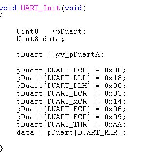
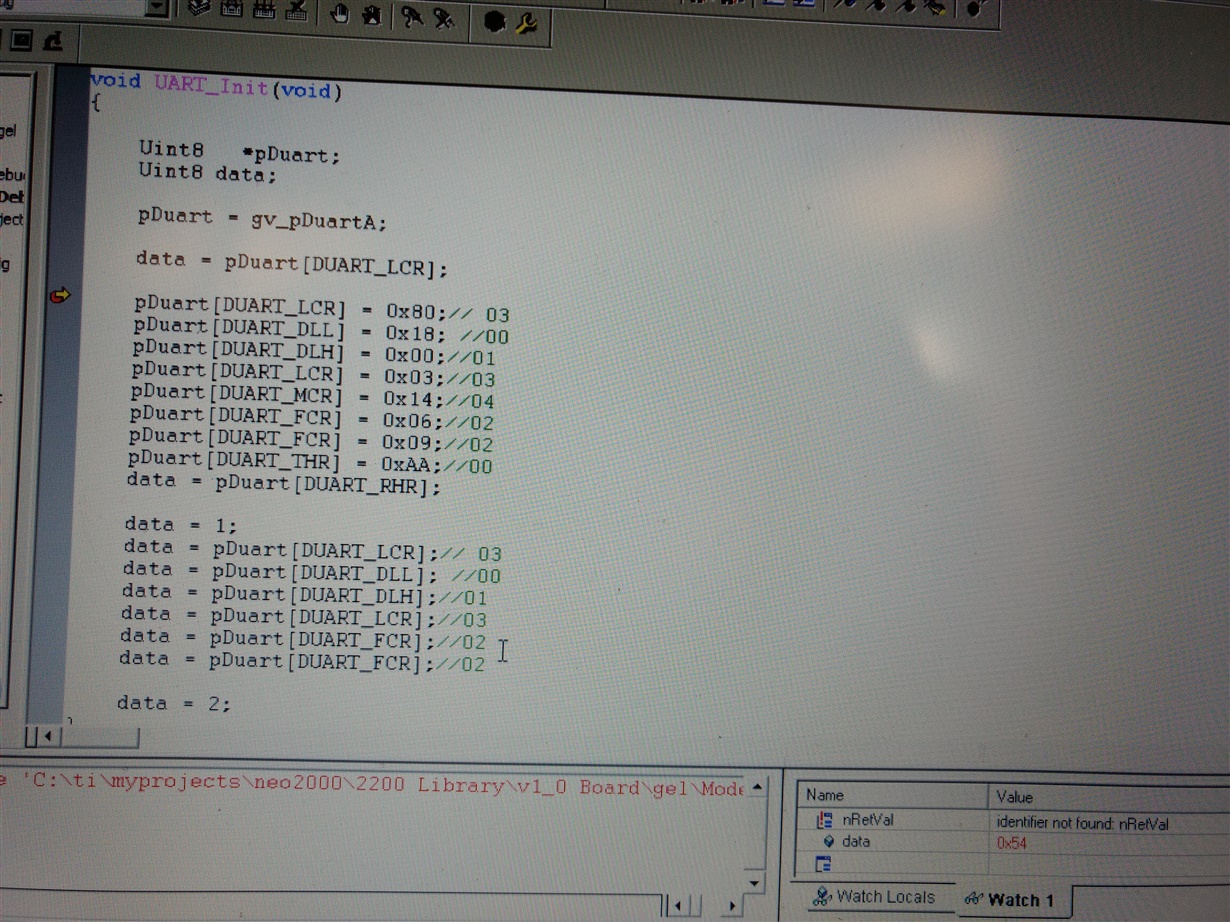
  • I have executed the same code to transmit 0xAA but I am receiving 0 only from RHR register. Attached image is the piece of code. I have also attached UART.h file which gives the indexes of all the DUART registers.


    Regards,

    AnujUART.h

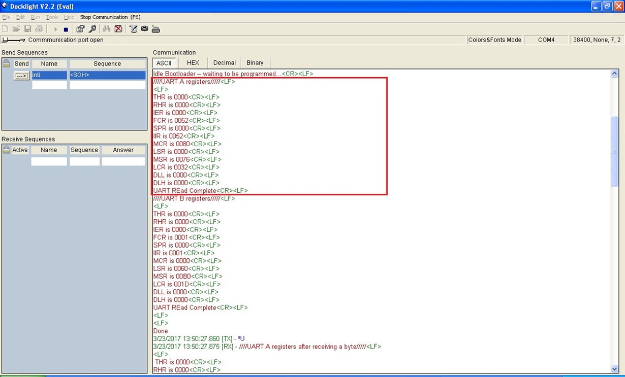
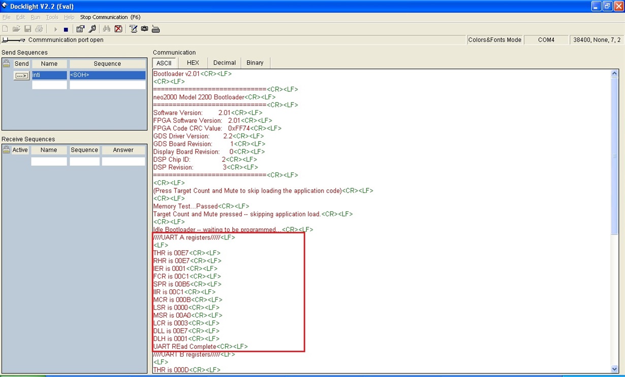
    I read out the DUART configuration registers from both old Master board (with TL16C752B) and new Master board (with TL16C752C) using the same Source Code and the new DUART register values are not matching with old DUART register values. In new GDS board, I am configuring the DUART for 8 data bits, 1 stop bit and no parity but when I read the configuration register back, it updates configuration as 7 data bits, 2 stop bits and even parity.

  • Hello Tom

    Thank you so much for your feedback! I would like to know if possible to get some screenshots with an oscilloscope of the signals A[0], /CS, /IOW and D[0] when you write the data in UART and when you will read, take /IOR instead of /IOW. Please, perform a double check of the voltage levels in Vcc pin, reset (must be low level) and also the amplitude of the XTAL signal. For your comments, looks like the UART doesn't receive the data. When you start to program the UART, first check the register 0x03 (LCR) and this one, must have 0x1D value. If you can confirm this before, continue programing the last code that I sent you. I have similar set up like you and I don't have any problem.

    Please, send me the screenshots
    Regards
    Francisco
  • Hello Francisco,

    I am the firmware engineer working on this project.

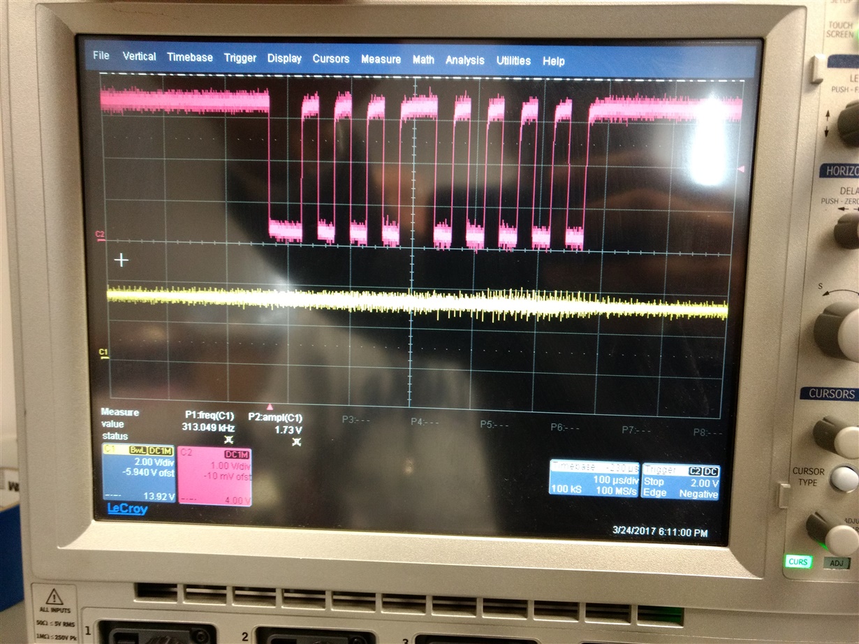
    We confirmed the voltage levels at Vcc pin, Rx and Tx pins and it is 3.3 volts. We also confirmed the reset line and it 0 V. I have attached "Rx data.jpg" image which displays the voltage level of Rx line.

    I also verified the LCR register value as you suggested and I read the value as 0x54. Below screens provides the code in debug mode and the value read out.

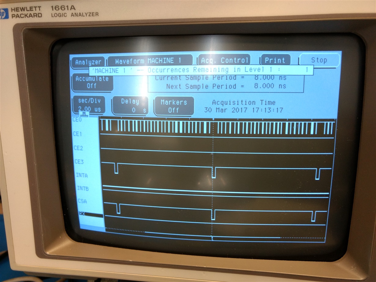
    Same we verified with logic analyzer and following is the screen:

    Above image also updates on IOR, IOW, Data Lines, address Lines and Chip select lines.

    Another update on this issue is - As I told we have old working board with TL16C752B  part so we swapped the TL16C752B part on Old Board with another new TL16C752C part and the old Board is receiving and transmitting the data perfectly. Even I executed this loop back test code with old board (with TL16C752C DUART part) and this test is also passed.

    Regards,

    Anuj

  • Hello Anuj

    For the value of the register, it looks like doesn't work well, but for your signals, it looks like is working.

    Did you test other samples of the same version? Do you know if necessary to use the C version? Because our most newer device is the D version.

    If possible, Can you test with this version?

    When you read different values in some registers like LCR the problem is the power supply or clock amplitude or frequency, but in this case everything looks good.

    So in my opinion, you can test other sample or test with our version D.

    Please, let me know your comments

    Regards

    Francisco

  • Hello Anuj

    Excuse me, do you have some news regarding this one? Did you test our version D?

    Please, let me know
    Regards
    Francisco

  • Hello Francisco,

    We have not yet tested the version D part but today I tested version C part with respect to interrupt line and following is my test case and result:

    Case 1: Receive Interrupt is not enabled and reading the IIR register in while loop until Interrupt is cleared
    Below image displays the Code which is the part of UART.c file which we shared previously:

    Result:

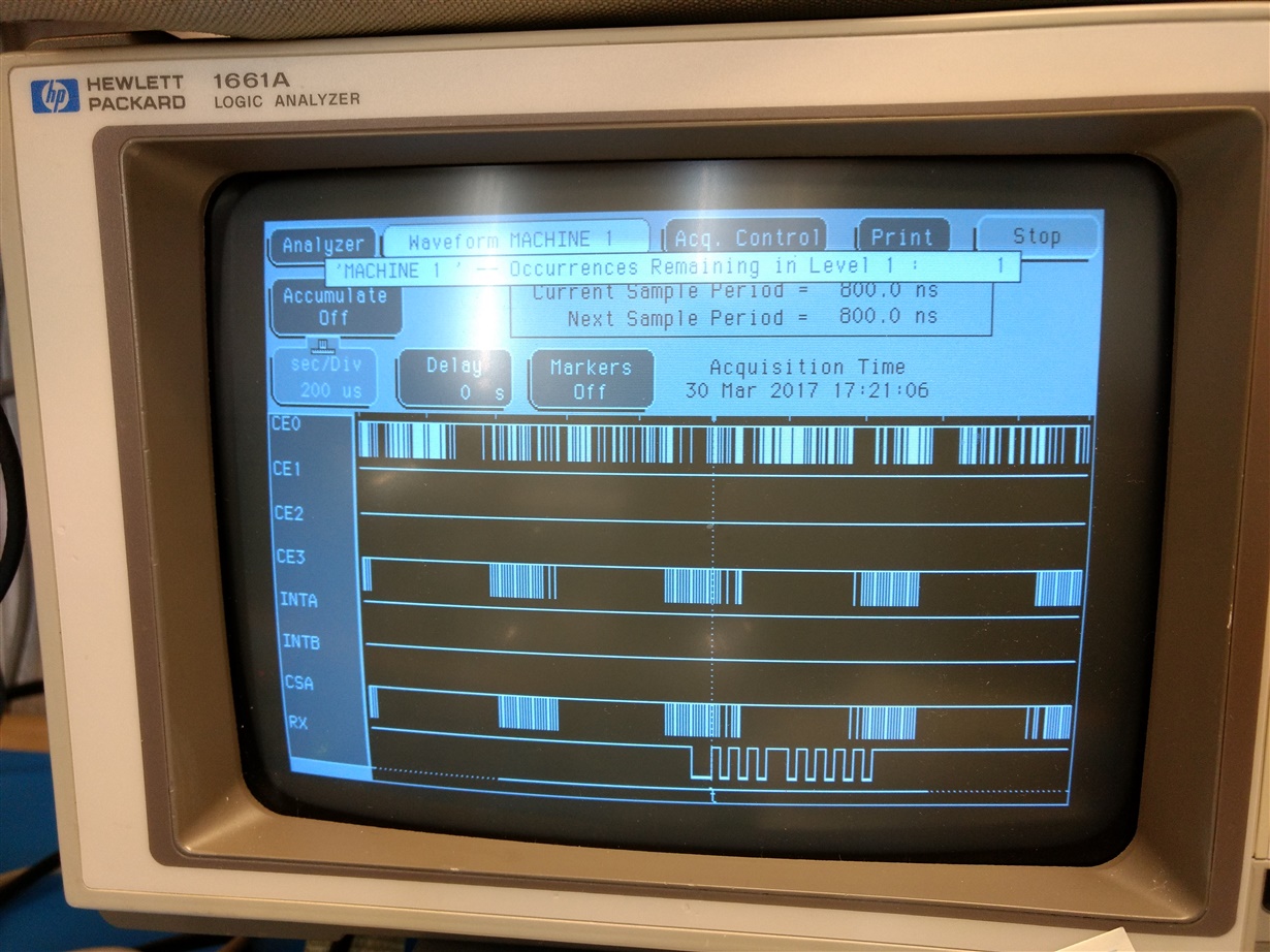
    Rx line is always high

    Interrupt A line is always low

    Chip select line is going low as per functionality

    IIR register returns value as 0x3B (not sure what it depicts) and the interrupt is never getting cleared so not coming out if while loop.

    Below is the logic analyzer image which displays Rx line as "RX", chip select line as "CSA" and Interrupt line as "INT A". I also traced CE0 - Interfaced to SDRAM, CE1 - Interfaced to Flash, CE2 - Interfaced to FPGA, CE3 - Interfaced to FPGA which generated CSA signal and CSA signal is input to DUART chip.

    Case 2:

    In continuation of case 1, transmitting the data continuously through PC,

    Result:

    IIR register is returning the same value 0x3B.
    Rx line is displaying the data transmitted through PC.
    Interrupt line is always low.

    Case 3:

    Enabled the receive interrupt and then reading the IIR register in while loop until interrupt is cleared
    Below image displays the code:

    Result:

    RX line displays the data sent by PC
    Interrupt is high
    IIR register is providing the same value 0x3B and interrupt is never getting cleared so not coming out of while loop.
    Chip select line is going low as per functionality
    Below is the logic analyzer image:

    Please check and analyze the values of IIR register mentioned in above cases.

    Thanks,

    Anuj

  • Hello Anuj

    Thank you for your feedback, is a very good test!
    I know that you told me from the beginning that this interface and the program works well with our last version, but I don't know if possible to do the same test but taken: Data[0:7], CSA, IOR, IOW, RxA, INTA, Address [0:2].
    I didn't see in the code the part where you have to send a logic 0 when you want to read or write. Is weird the value of the IIR register because the default value is 0x01, if you start to read the UART without any configuration, you must to read this value also in case of the LCR register, you must to read 0x1D.
    I am still testing here and analyzing whats going on.

    Regards
    Francisco
  • Hello Anuj

    Please, let me know if you have some feedback.

    Regards
    Francisco
  • Hello Francisco,

    Following is summary of EMIF interfaces with DSP C6711:

    SDRAM has been mapped at 0x8000 0000 address same as old system, ECLCKOUT is 100 MHZ

    Flash has been mapped at 0x9000 0000 address same as old system

    FPGA has been mapped at 0xA000 0000 address same as old system

    DUART has been mapped at 0xB000 0000 address same as old system.

    DSP's CLKIN is 150 MHz.

    I was debugging further this morning on this issue and I am looking at the memory address 0xB000 0000 to know about the values of DUART registers using the "View Memory" option of Code Composer Studio 3.0 IDE . I was executing the loop back code line by line using the breakpoints. Initially Loop back code writes the 0x80 value in LCR register and I can see this values is getting written at 4th Byte of 0xB000 0000 address location. Then after writing DLL and DLH in loop back test code, LCR is written with 0x03 and this 0x03 has also been written successfully at 4th Byte of 0xB000 0000 location. After this step, MCR is getting updated with 0x14 value. I verified the 0xB000 0000 address location again just after writing the 0x14 value in MCR and LCR value is completely changed from 0x03 to some other value. 

    I executed the above test code with old DUART part on old system and this LCR value corruption is not happening there. Can you please suggest something helpful by this test case results.

    When I executed above test case, initially i was able to debug the code but later debugging is not taking place. Debugging is never appearing to main() function. Debugging is taking place on old system with same Source Code and same Gel file. Would you please assist on this also.

    Regards,

    Anuj

  • Hello Francisco,

    As we have to start the production of boards so we have to close the issue at the earliest. Is it possible to discuss this issue over call or it would also be helpful for us if it can be debugged by TI FAE at our site.

    Debugger issue has completely stopped us now to go further and debug the UART issue.

    Regards,

    Anuj

  • Hello Anuj


    I think could be very useful to have a call. Please, send me an email at francisco.zamudio at ti .com and we can schedule a meeting.

    Regards
    Francisco
  • Hello Francisco,

    Thanks for the discussion in call.

    As per our discussion, We connected another board and read out the default configuration values of LCR and IIR register and part does not provide default values as "1D" and "01" respectively. Further I transmitted some bytes from PC to the board and it is still receiving "0".

    We then removed the TL16C752C part and mounted TL16C752B part and verified the functionality. And this combination (new design + Old DUART part) is working fine. DSP is receiving the data sent to DUART chip.

    Can you please update - TL16C752C part is the perfect pick and drop part for TL16C752B ? Do we need to modify the firmware to support the TL16C752C part ?

    Do you want us to ship the non working TL16C752C chip for your analysis.

    Regards,
    Anuj
  • Hello Anuj

    Thank you so much for your feedback, I will send you details by email. Let me check your samples when they arrived and I will send you our feedback. We have to analyses the samples.

    Regards
    Francisco