This thread has been locked.

If you have a related question, please click the "Ask a related question" button in the top right corner. The newly created question will be automatically linked to this question.

TRS3122E: Some questions on TRS3122E

Part Number: TRS3122E

Hi Sirs,

Sorry to bother you.

We have some questions on TRS3122E.

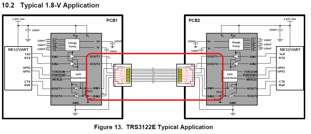
1. Please help check our function block is OK ??

2  Does TRS3122ERGER have support level shift function on 1.8V to 3.3V?? If yes, we could remove up board level shift IC.

3. Do we need add one more TRS3122ERGER on down board side? The cable around one meter

4. Do we need to swap our TX/RX between up board & down board?

    ex: up board TX --> down board RX

          up board RX --> down board TX

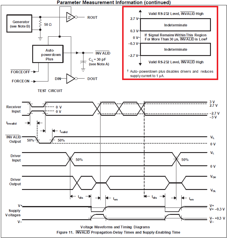
5. What is fig 11 red circle mean? The normal working rating? or the TRS3122E output swing will between +2.7V~-2.7V??

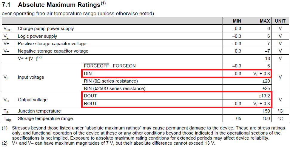
6. The UART input/output power rate as below red circle??

    For now our VL is 3.3v, so the UART power rate will be 3.6v?

Thanks!!

  • Hi Shu-Cheng,

    thanks for reaching out. Let me try to answer your questions breifly.

    2  Does TRS3122ERGER have support level shift function on 1.8V to 3.3V?? If yes, we could remove up board level shift IC.

    -> The VL and Vcc voltage levels of the TRS3122E can be different. Powering the device with 3.3 V and operating at 1.8 V logic levels works. So no level shifter is needed.

    3. Do we need add one more TRS3122ERGER on down board side? The cable around one meter

    -> Yes for a transmission always a transceiver and a receiver is necessary as shown on Fig. 13. Basically PCB1 is your up bard PCB2 is the down board.

    4. Do we need to swap our TX/RX between up board & down board?

    -> Yes the transceiver DOUT (TX) is connected to the receiver RIN (RX)

    5. What is fig 11 red circle mean? The normal working rating? or the TRS3122E output swing will between +2.7V~-2.7V?

    -> This describes the BUS signal interpretation. The differential BUS signal will be received correct if the swing is above 2.7 V and below -2.7 V

    6. The UART input/output power rate as below red circle??

    -> For example if you operate with 1.8 V logic levels, the VL pin must be provided 1.8 V. Then the signals from the CPU have be in the range of min -0.3 V to max 2.1 V in order not to damage the TRS3122E.


    Let me know if this is helping you out. Don't hesitate to ask further questions.

    Kind regards 

    Dierk