This thread has been locked.

If you have a related question, please click the "Ask a related question" button in the top right corner. The newly created question will be automatically linked to this question.

TPS65982-EVM: Daisy Chaining and the Application Customization Tool

Part Number: TPS65982-EVM
Other Parts Discussed in Thread: TPS65982, TPS65983B

I have some hardware en software questions. 

I am trying to daisy chain multiple TPS65982 but the documentation is not really clear about it. Also I am trying to figuring out the Application Customization Tool. But the documentation is not consistent with version 2.15. 

Here are my questions:

Hardware

1. I want to daisy chain the TPS65982, but the datasheet is not clear about it: How many can you daisy chain?

2. And how? I am guessing TX of the 'master' on the RX on the slave and so on. But when i'm reading the datasheet i get confused. 
UART_TX is @ POR a UART_RX and you have to Connect UART_TX to the TX of the next device. But i also have to connect the UART_RX to the TX.

E2 UART_TX Digital output Port multiplexer pins UART_RX UART serial transmit data. Connect pin to another TPS65982 UART_TX to share firmware. Connect UART_RX to UART_TX when not connected to another TPS65982
F2 UART_RX Digital input Port multiplexer pins Digital input UART serial receive data. Connect pin to another TPS65982 UART_TX to share firmware. Connect UART_RX to UART_TX when not connected to another TPS65982 and ground pin through a 100-kΩ resistance.

3. In daisy chain, should ever device boot at the same time to load the firmware? Or is is possible for example chip 2 to load the firmware 5 min later? To do this, should de TX of the last device connected to the RX of the master device?   

Application Customization Tool: 

4. Device Initialization Chain: 
In the manual (slvuar8a) I find this: 'Allows user to save unique configurations for up to three devices in a single image to flash simultaneously (through UART)'  But I can only select 2 instead of 3. Is this also how many device I can daisy chain? Or are that in total 8. Because the datasheet talks about 7 slave adresses. (datasheet: Page 79)

SPI Owner, UART Master 0 (Primary) 0 Ω 0x00
UART Slave 7 38.3 kΩ 0x01
UART Slave 6 84.5 kΩ 0x02
UART Slave 5 140 kΩ 0x03
UART Slave 4 205 kΩ 0x04
UART Slave 3 280 kΩ 0x05
UART Slave 2 374 kΩ 0x06
UART Slave 1 (Secondary) Open 0x07

5. Configuration Data Sets: 
I can select 6 configuration sets, This are sets I can choose by a GPIO to load when the system boots? Is this the same as the configurations seen in slvuaf8c (page 13) ? But that are 16 different configurations... How is this been done? Or is this something else

6. Configuration Data Sets: 
What are the function of the Virtual pin strap settings? 

7. Where can I find the project file for the EVM module instead of the binary? 

Kind regards,

Pieter

  • Hi Pieter,

    I will look into your questions are reply asap.

    Thanks

  • Hi Pieter,

    I have attached a QandA document to answer your questions. Please let me know if I didnt clearly answer any of your questions. Also let me know if you are not able to flash the secondary, I will further assist.secondary UART flash QandA.docx

    Thanks

  • Thank you for your answer , totally missed the 2 device text. But I have some additional questions:

    - In the Pin Functions you will see the por state of every pin. And UART_TX say's UART_RX @ POR
    - So if i understand it right: Primary TX to Secondary RX and Secondary TX to Primary RX?
    - To be sure: If I give every TPS65982 the it's own flash, (we are looking into 7 UCB-C connectoren) I need 7 different I2C addresses. So i need to use the i2c_address pin.
    If I understand it right: It will not deliver any problems if I put the TPS65982 for example in 'UART Slave 5' to get address 0x03 on i2c because the MISO pin will be high @ boot? So it will still load  the config from the flash? Or it must always be in "SPI Owner, UART Master 0 (Primary)" when the TPS65982 has its own flash. 

    - If i am not using daisy chain, what to do with the UART_TX and RX?  EVM leaving them floating, datasheet say's @ TX: 'Connect UART_RX to UART_TX when not connected to another TPS65982'  and @ RX 'Connect UART_RX to UART_TX when not connected to another TPS65982 and ground pin through a 100-kΩ resistance. So short RX and TX en connect it through a 100k to ground? 


    Thanks

    Pieter

  • Hi Pieter,

    Thanks for the follow up, I attached the answers again in a word doc for convience. Let me know if you need any more help!  

    secondary UART followup QandA.docx

    Thanks

  • Hi Jeffery,

    Thanks for you quick answer. I really appreciate it :-) 

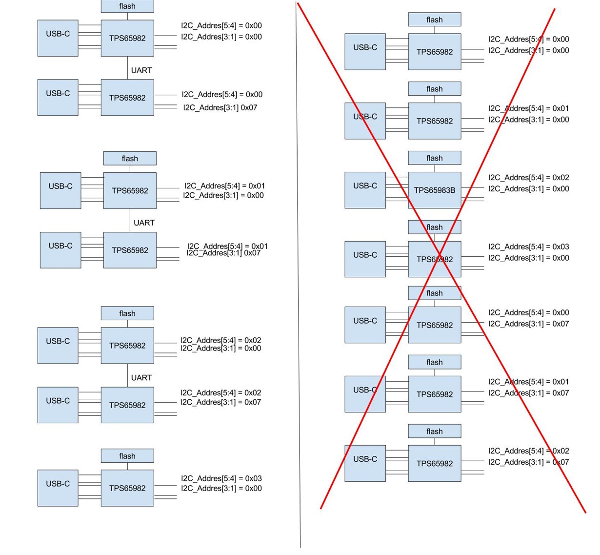
    To confirm your explanation if I understand it right, I send a image:

    Left is possible, right side is not because the last 3 devices does not put the device is SPI owner mode (because of the i2c address), so it cant read the flash.

    Kind regards,

    Pieter

  • Hi Pieter,

    Great clarification pic.

    note: DEBUG_CTRL1/2 are used in order to create more than 7 possible unique addresses for further flexibility in a system. DEBUG_CTRL1/2 do not nessesseraly have to be used in your case because the 7 virtual addresses are there.   

    not working case:

    Correct, in this case the bottom 3 will not BOOT because it will be trying to use UART (it is a UART slave secondary) and wont be connected to SPI flash.

    working case:

    The left side is Ideal. Each pair has a primary 0x00 and a secondary 0x07. each pair also has a unique address from DEBUG_CTRL1/2 0x00, 0x01,0x02,0x03 for each primary/secondary. note: the last one is not using UART which is also correct.

    Let me know if you need anymore help with this interesting application!

    Thanks

  • Hi Jeff,

    Thanks for you answer. 

    Is the TPS65982 also going to be in a PD3.0 version? The charge status of the battery is very interesting function. I see the TPS65983B already supports it, the chips seem identical if I compare them both.

    Kind Regards,

    Pieter

  • Hi Pieter,

    The TPS65982 is a PD2.0 component. There would need to be hardware changes to the Si to make it a PD3.0 chip.
    The TPS65983B is our catalog PD3.0 component that supports the battery charge status function as well as other PD3.0 features.

    Thank you,
    Eric
  • Hi Eric,

    Thank you for replying

    So they are te same in functions but one support 3.0? Because the datasheet say's that this one is for thunderbolt devices, but i can't find specific specs in the overview why that is. They seems the same...

    Pieter