This thread has been locked.

If you have a related question, please click the "Ask a related question" button in the top right corner. The newly created question will be automatically linked to this question.

TUSB2077A: !PWRON-signals always high, no downstream connection possible

Part Number: TUSB2077A
Other Parts Discussed in Thread: TPS2062

Hi,

I have a prototype design with the USB hub mentioned in the title, configured as self-powered, non-ganged.

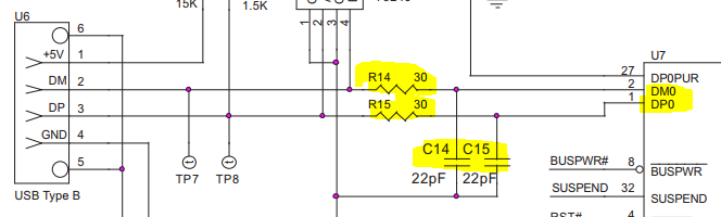
My issue is that I can't get the downstream ports to work since the !PWRON-signals stay high all the time. I already noticed that the power switches TPS2066D have active high inputs, thus the current configuration doesn't work. I replaced them with TPS2062 devices, which incorporate an active low logic at the input pins. As this didn't solve the problem my idea was that the power-up sequence is wrong (the low signal at the reset pin at power-up is too short). I inspected this with a scope, a screen capture is attached. The schematic is attached as well.

If you could take a look at the schematic and the power-up timing I'd appreciate it.

Thanks in advance!
Tim

Schematic TUSB2077A.pdf

  • Addition: the hub itself is recognized by the PC (appears in the device manager). I did some further debugging and found that SUSPND is always HIGH.
  • Hello Tim,

    I am reviewing your e=schematic and will be providing additional feedback soon.

    Regards,
    Jorge
  • Hello Tim,

    I would recommend to adjust your initialization routine to comply with the datasheet recommendations:

    "Reset with a pulse width between 100 μs and 1 ms is recommended after 3.3-V VCC reaches its 90%. Clock signal has to be active during the last 60 μs of the reset window"

    Additionally, all USB DP/DM signal pairs require series resistors of approximately 27Ω to ensure proper termination. An optional filter capacitor of about 22 pF is recommended for EMI suppression. This capacitor, if used, must be placed between the hub terminal and the series resistor, as per section 7.1.6 of the USB specification.

    Additionally all USB differential signals on the DS ports should have a 15k PD as specified on the DS and evaluation module schematics.

    http://www.ti.com/lit/ug/sllu190/sllu190.pdf

  • Hello Jorge,

    thank you very much for your feedback on my design. I will implement the series resistors, EMI capacitors and pulldown-resistors. I somehow missed them when I 

    One further question: As you can see in the schematic I didn't implement any kind of control logic or µC for the initialization routine but a resistor and a capacitor. Do you think that the initialization and especially the choice of the resistor and capacitor values rather than the missing components at the DP/DM signals is the critical part of my problem? If so, could you please suggest alternative values?

    Thanks again for the quick reply!

    Tim

  • I probably should have mentioned that Windows occasionally notifies me of a power surge on the USB Hub ("USB device has exceeded the power limits of its hub port" or "Power Surge on Hub Port"). Could this be a sign of e.g. a short circuit (I'm pretty sure that I've checked that) or a wrong PCB layout? This error message also appears when there's no USB device connected to the hub. Thank you!
  • Hello Tim,

    The TUSB2077 does not have internal pullups in OVRCUR terminals. Please, connect OVRCUR pins to Vcc using 10kOhm resistors.

    Regards
  • Hello Joel,

    your hint solved the problem. Thank you really much!

    Regards
    Tim