This thread has been locked.

If you have a related question, please click the "Ask a related question" button in the top right corner. The newly created question will be automatically linked to this question.

TUSB8041A: Getting the downstream ports of the HUB into CDP mode

Part Number: TUSB8041A
Other Parts Discussed in Thread: TUSB8041

Hello,


We are having an issue getting the downstream ports of the HUB into CDP mode.  The HUB works in CDP mode when not connected to the PC Host.  When we use Windows to make the connection upstream we lose CDP mode on our downstream ports.  We believe this is not a TUSB80xx problem but are not sure where to look in Windows to ensure that it enables CDP mode.  Are you familiar with tools or steps in Windows to have this work?


Thanks,


Zack

  • Hi Zack,

    When the upstream port is disconnected and battery charging is enabled, the downstream ports will be in DCP mode. When the upstream port is connected and battery charging is enabled, the downstream port will be in CDP mode. What is the setting of AUTOENz in your system? How are you determining if CDP is enabled or not?

    Regards,
    JMMN
  • Hi JMMN,

    We have a tester (www.passmark.com/.../usb-power-delivery-tester.htm) that allows us to determine the charge mode of a USB port. AUTOENz is tied to ground on default and we have also tied it to 3.3 V and neither have worked for us.

    Thanks,
    Zack
  • Hi Zack,

    If battery charging is enabled on a port and the upstream port is connected, the downstream ports will automatically enter CDP mode if the downstream device does the correct CDP handshake per the USB BC 1.2 specification. We have verified this with two different USB BC compliance test tools. I am not familiar with the PassMark tool, does it perform the CDP handshake to enable the charging mode?

    Regards,
    JMMN
  • TUSB8041dump.txt
    Export Time: 2018-03-06 16:49:43
    Port 0
    Adapter HW_Version: 3.00 FW_Version: 3.50
    
    "Time","Module","Read/Write","Master/Slave","Features","Bitrate","Address","Length","Data"
    "2018-03-06 16:49:18.984","I2C","RegW","M","---","100","0x44","1","00"
    "2018-03-06 16:49:18.984","I2C","RegR","M","---","100","0x44","256","00 51 04 40 81 10 0C 0F 0F 00 02 00 00 00 00 00 02 40 00 41 81 89 F3 23 DA 15 8F C2 B6 C9 D0 00 09 04 18 00 00 00 00 00 00 00 00 00 00 00 00 00 30 00 34 00 30 00 34 00 30 00 30 00 35 00 39 00 30 00 33 00 39 00 32 00 00 00 00 00 00 00 00 00 00 00 00 00 00 00 00 00 00 00 00 00 00 00 00 00 00 00 00 00 00 00 00 00 00 00 00 00 00 00 00 00 00 00 00 00 00 00 00 00 00 00 00 00 00 00 00 00 00 00 00 00 00 00 00 00 00 00 00 00 00 00 00 00 00 00 00 00 00 00 00 00 00 00 00 00 00 00 00 00 00 00 00 00 00 00 00 00 00 00 00 00 00 00 00 00 00 00 00 00 00 00 00 00 00 00 00 00 00 00 00 00 00 00 00 00 00 00 00 00 00 00 00 00 00 00 00 00 1E 1E 1E 1E 1E 00 00 00 18 18 18 18 18 00 00 00 04 04 04 04 04 00 00 00 77 77 77 77 77 00 00 00 00 00 00 00 80 80 80 80 01 12 00 00 00 00 00 00"
    "2018-03-06 16:49:30.627","I2C","RegW","M","---","100","0x44","1","00"
    "2018-03-06 16:49:30.627","I2C","RegR","M","---","100","0x44","256","00 51 04 40 81 10 0C 0F 0F 00 02 00 00 00 00 00 02 40 00 41 81 89 F3 23 DA 15 8F C2 B6 C9 D0 00 09 04 18 00 00 00 00 00 00 00 00 00 00 00 00 00 30 00 34 00 30 00 34 00 30 00 30 00 35 00 39 00 30 00 33 00 39 00 32 00 00 00 00 00 00 00 00 00 00 00 00 00 00 00 00 00 00 00 00 00 00 00 00 00 00 00 00 00 00 00 00 00 00 00 00 00 00 00 00 00 00 00 00 00 00 00 00 00 00 00 00 00 00 00 00 00 00 00 00 00 00 00 00 00 00 00 00 00 00 00 00 00 00 00 00 00 00 00 00 00 00 00 00 00 00 00 00 00 00 00 00 00 00 00 00 00 00 00 00 00 00 00 00 00 00 00 00 00 00 00 00 00 00 00 00 00 00 00 00 00 00 00 00 00 00 00 00 00 00 00 00 00 00 00 00 00 1E 1E 1E 1E 1E 00 00 00 18 18 18 18 18 00 00 00 04 04 04 04 04 00 00 00 77 77 77 77 77 00 00 00 00 00 00 00 80 80 80 80 01 12 00 00 00 00 00 00"
    
    Hello

    Are you available to have a call with the customer on this issue?  I have attached a log of the SMBUS register reads of the device when the host is connected and conversely when the host is not connected (You will have to rename it to csv to view).  It is our understanding that our test tool does the CDP handshake to enable charging mode as we have tested this on other non-TI hubs and it works when the host is disconnected or connected.

    In my attached spreadsheet,row 7 is when the host is connected.  Row 9 is when the host is disconnected.  What I see is that the configuration is identical so I am not sure where to look next.  I think your guidance is appreciated.  

  • Hi Jason,

    There are no status registers in the TUSB8041 so I would not expect the values read back to change. The hub is configured using EEPROM / SMBUS or pin configuration at power on reset and does not update its configuration until the next power on reset. Can you post a copy of the customer schematic? The TUSB8041 needs to have battery charging enabled at power on reset via pin configuration or EEPROM / SMBUS and it must be able to control VBUS to change from DCP to CDP mode. I would also like to see a failing CDP test log versus a passing CDP test log.

    Regards,
    JMMN
  • Hello,

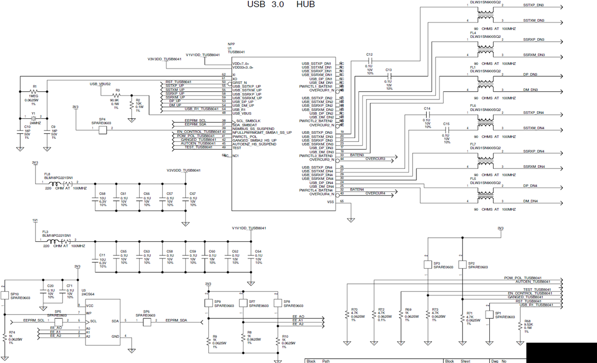
    Below is the schematics for your review.  If you need more detailed schematics please contact me at Jason Haedt in the address book.  Currently we are not using an EEPROM and SMBUS. The EEPROM below is not installed so we are relying on the hard lines for proper configuration.  I have currently grounded pin 39 to enable SMBUS mode so I can read out the configuration registers.  

    Not shown are the load switches present in the design.  These use the BATFET enable lines.  The CDP mode works when no host is connected but no longer works as soon as a host is connected.  So we know the load switches are working properly. 

  • Hi Jason,

    CDP charging mode is when the upstream port of the hub is connected to a host and configured. DCP charging mode is when the upstream port of the hub is not connected. When the hub goes from unconnected to connected, the VBUS on the downstream ports needs to be toggled low to force the downstream devices to exit DCP mode and enter CDP mode - do you see that occur?

    Regards,
    JMMN
  • Hi

    Is there any update?
  • Hello,

    Jason and I have some updates but we would prefer to take them offline. Could you send me (Zack Schwarz) an email and we can go from there?

    Thanks,
    Zack
  • Hello JMMN,

    Please contact Zack Schwarz on TI email. We would like to share more information.

    Something we noticed early on was that there is some conflicting information in the datasheet. The circuit in our hardware is configured as specified by the datasheet, which calls out the actual resistor values. On our board, I am measuring about 0.5V on USB_VBUS when USB_VBUS2 is connected to the 5V host.

    Table 1 from the datasheet specifies >4V on VBUS for CDP mode yet the maximum recommended voltage is 1.155V.

    It is pretty easy to assume, the mistake is the >4V spec but maybe this is worth looking into based on what we are observing.

    Sincerely,
    Jason
  • Hi Jason,

    The USB_VBUS pin is a VBUS sensing pin.

    I am closing this ticket since we are handling through direct email.

    Regards,
    JMMN