This thread has been locked.

If you have a related question, please click the "Ask a related question" button in the top right corner. The newly created question will be automatically linked to this question.

TPS2546EVM-064: Unable to switch between current limits

Part Number: TPS2546EVM-064
Other Parts Discussed in Thread: TPS2546

Hello, hoping to get some pointers or advice on using this evaluation board.  I have been trying to switch between SDP2 and CDP mode (1110 to 1111) and am getting some weird results.  I have replaced the 80k resistor with a 210k resistor to achieve a current limit of ~240mA.  Here is a quick summary of what happens during my tests:

SETUP: USB data line capable of 1.5A into EVM, EVM to Android tablet

1. Start up in 1111 mode, measured about 1.3A going to the tablet.  Everything is good, data communication works.

2. Plug in jumper for ILIM_SEL to switch to 1110 mode, measure about 250mA, data still working.

3. Unplug jumper for ILIM_SEL to switch back to 1111 mode,  The current reads roughly 550mA, data still working.  It doesn't get back to 1.3A charging current unless I reset the chip with the EN pin.

Is the chip capable of switching back to the higher current fully or am I missing something?

I also tried to switch to a much bigger resister for ILIM_LO (604k).  On startup, it seems to work, measuring about 100mA with working data communication.  However removing and reconnecting the ILIM_SEL jumper doesn't seem to do anything, the charging current stays at 100mA.  Is the current limit too low for the chip to switch?  It does say the resistor limits are 16.9k to 750k in the datasheet.

  • Hi Jeffrey,

    I see this is your first post. Welcome to E2E!

    I have not heard this problem before and was unfortunately unable to replicate the issue with an EVM here in the lab. However, this is not a practical use case. Once the BC1.2 negotiation is complete, and the device starts charging, the mode in which the device is charging at will not change. So there is no need to switch from CDP mode to SDP mode and then back to CDP mode mid charge.

    With that being said, would you mind explaining your system a little but more? What are your hoping to accomplish and what is your end application?
  • Hi Adam, thank you for the response and sorry about the delayed reply.

    In my system, I have a main lithium battery that powers the main motherboard, a tablet, as well as a couple of other components. The motherboard maintains communication with the tablet that is being charged through the TPS2546 chip. The motherboard also has a small backup battery to power itself and the tablet in the case where the main battery gets completely drained and no one is there in time to swap it. I want to maintain the communication in this case, but in order to maximum the use time of the backup battery, I want to decrease the tablet charging to a minimum until the main battery can be replaced. This is the main reason why I want to switch between ILIM_HI and ILIM_LO. Increasing the size of the backup battery isn't possible due to size and weight constraints.

    Would it be an issue if I test with a USB data line that can supply 1.5A and feed in an external 5V to the V_in at the same time?
  • Hey Jeffrey,

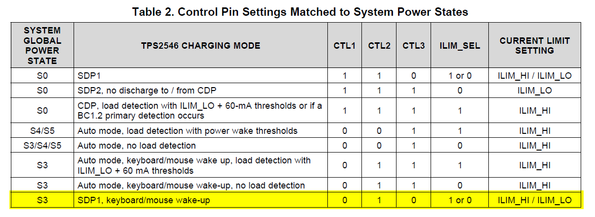
    In that case, what I would recommend you do is take advantage of the different power states of the TPS2546. S0 is standard power state while S3 is a low power state. Table 2 in the datasheet shows the configurations for each power state. I would recommend you go on the last power state when your system starts to run off of the backup battery.

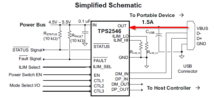
    Are you asking if you can supply 1.5A into OUT while also supplying 5V to the power bus? If that is your question, no you cannot do that, it will break the TPS2546.

  • Thanks Adam, I will test that out.

    Regarding the power in, I was referring to the IN pin, but I looked at the schematics and it looks like it's fine to do that as long as they are power sources with a common ground.