This thread has been locked.

If you have a related question, please click the "Ask a related question" button in the top right corner. The newly created question will be automatically linked to this question.

TXB0104: Power calculation

Part Number: TXB0104
Other Parts Discussed in Thread: ASH,

Hi,

I am using this part in my circuit, and i want to know how much total current consumption for this part?I am operating this device to convert 3.3V to 2.5V

I am calculating total power consumption for entire board so I want to measure Total power dissipation of Level translator.

Can anyone share me calculation ?

Thanks

Ash

  • Hello Ash,

    I would recommend reading through the application report 'A Guide to Voltage Translation With TXB-Type Translators' to better understand how they work, then you can use the equations found in the application report 'CMOS Power Consumption and Cpd Calculation' to calculate the total power consumed.

  • HI,

    I was going through the above mention document and in" CMOS Power Consumption and Cpd Calculation(scaa035b)" document page 8 , it is mention as In the case of single-bit switching, NSW in equation 4 is 1.

    I want to know when NSW can be 2 in equation 4(page 8).

    Thanks
    Ash
  • NSW indicates the number of bits that are switching -- if you have 2 channels that are both switching at the same frequency, you can use that equation with NSW = 2.  If your channels are operating at different frequencies, you can sum the results of two separate calculations with NSW = 1.

  • HI,


    Thanks for your reply.
    I completely gone through the ablove two documents and it help to improve my basics but still i am not able to complete the calculation of power dissipation of IC.

    Total power dissipation=static PD+Dynamic PD

    Problem 1:-
    Statis PD=VCC*ICC
    But here we have two different voltage bank VCCA and VCCB, how to calculate the static PD ?

    Dynamic power calculation is also not clear to me .

    Problem2:-The transient power calculation will be done by 6.16 page 10 but my signal are bidirectional so which Cpd need to be selected I donot know ?


    Problem3:- Capacitive load Power consumption-
    This level translator one end is getting connected to SoC and other end is connected to ti TS3A5018PWR MUX.
    Which side i need to take load capacitance?

    Thanks
    Ashu
  • Hi Ash,

    Thanks for reading through both of those documents, I think it will make it easier for me to explain.

    The TXB0104 is more complex than a single logic gate, but the same basic power calculations apply.

    The red lines above indicate connections to the A supply, and the blue lines indicate connections to the B supply. When the device is in the static state (ie is not switching) the drivers labelled 'A' (forgive my bad handwriting) are turned off, and the drivers labelled 'B' are driving the lines through the 4kΩ resistors.

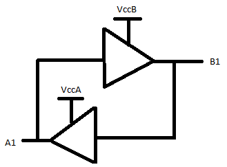
    Essentially, you can look at this as two buffers - one sourced from VccA and outputting to the A1 side, and one sourced from VccB and outtputting to the B1 side.

    The 4kΩ resistors should only factor into your power calculations if the line is driving some load (other than a normal CMOS input). Typically the current on a CMOS input will be in the nanoamp region.

    Simplified schematic (again, forgive my bad drawing):