This thread has been locked.

If you have a related question, please click the "Ask a related question" button in the top right corner. The newly created question will be automatically linked to this question.

LSF0108: 100MHz SPI application using LSF0108

Part Number: LSF0108
Other Parts Discussed in Thread: SN74AVC4T774

Hello team,

Our customer is evaluting LSF0108 for one 100MHz SPI applicaiotn, so would you like to help us double check below questions?

1. SPI length constraint is 4000mils. If the signal pass through LSF0108PWR, the output SPI are re-estimate signals length, or not?

2. How to select pull up Rpu resistor?  In SPI case, input and output signals are both pull resistor, or not?

Thanks,

Antony

  • Hi Antony,
    If at all possible, the long traces should be placed on the "low" side of the LSF (the side with a lower voltage signal). Another way to say this is to put the LSF as physically close to the "high" side device as possible.

    The low-side pull-up resistors can be large - typically 10k is more than sufficient, and often they are not required at all (application dependent).

    For high-side pull-up resistor selection, there are two primary equations to balance. The resistors must be large enough to limit current for the drivers (I_OL of driving device), but small enough to provide fast edges for the desired data rate.

    R_PUb > V_B/I_OL
    R_PUb > 1/(6*C_P*D)

    With
    R_PUb = B-side pull-up resistor (ohms)
    V_B = B-side pull-up voltage value (V)
    I_OL = Lowest value between A and B side drivers' I_OL
    C_P = Parasitic capacitance on B side of LSF (trace capacitance + input capacitances)
    D = maximum data rate desired
  • SPI_VOLT_TRANS_PAGE (2).pdfHi Emrys,

    Many thanks.

    But the 100MHz is our  max supporting frequency, so we are also checking SN74AVC4T774, so whether we can support the loss or trace length of pre-channel and post-channel of SN74AVC4T774 and LSF0108?

    Thanks and Best Regards,  

    Antony Fu  

  • Hi Antony,
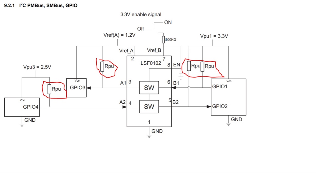
    The LSF0108 will not operate with the schematic shown. Please take a look at this thread: e2e.ti.com/.../632065

    It contains the correct way to use the enable pin on the LSF010x series of translators.

    Also, it looks like the pull-up resistor requirements might be reversed. For up-translation, a pull-up resistor _must_ be on the higher-voltage side of the LSF (B1, B2, B3). The lower-voltage side of the translator can have pull-ups as well, but they typically are not required (unless the low-side driver device is open-drain)
  • Also, we just released a video series that can help you to understand the LSF family better. It's available here:

    The Logic Minute