This thread has been locked.

If you have a related question, please click the "Ask a related question" button in the top right corner. The newly created question will be automatically linked to this question.

SN74AVC4T245: schematic review

Part Number: SN74AVC4T245
Other Parts Discussed in Thread: SN74AVCH4T245,

Hi team,

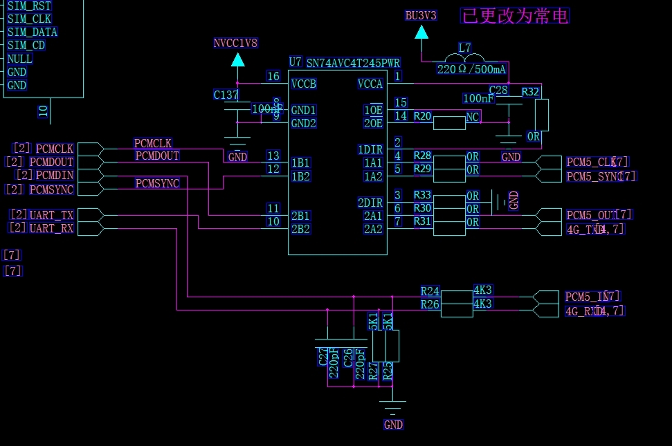
Could you help review below application circuit from my customer? The customer only uses port 1 for data communication, and port 2 is reserved.

  1. If the customer doesn't use port 2, 2OE must be connected to VCCA through a 10kohm resistor, is that correct?
  2. If port 2 is reserved, are there any requirements for the input/output signal of port 2?
  3. In customer's mass production products, they found 2 pcs device will have excess Icca current (about 4mA), do you think there is something to do with their design, or we need to do some IC level analysis? https://e2e.ti.com/support/logic/w/logicfaq/3539.04-power-thermals#Question02 According to this link, the increase of Icca is uA, not mA.

Best regards,

Dongbao

  • For question 2 and 3, get some information from https://e2e.ti.com/support/interface/voltage_level/f/391/t/588818?tisearch=e2e-sitesearch&keymatch=SN74AVC4T245, for unused port 2, either 2Ax or 2Bx  must be connected to GND. Do you think this may be the root cause of 2 pcs failure (excess current consumption Icca than the normal device)?

    Since this project has MP, can we solve this problem by replacing SN74AVC4T245 with SN74AVCH4T245? Or customer have to change their schematic/PCB?

    Best regards,

    Dongbao

  • Hello Dongbao,

    1. Yes, tie the OE pin high for port 2 to disable these ports.
    2. These ports still have inputs that must be defined to ensure that a floating input does not create excess current consumption. You should tie all the port 2 pins to GND to ensure there is no excess current due to shoot through current from VCC to GND.
    3. For certain devices, this shoot through current can be easily in the mA range, so this is not completely unexpected.

    If you cannot change the layout for use with this device, the drop in replacement of the SN74AVCH4T245 should work as it will ensure the unused inputs are in a defined state to limit shoot through current.
    If you use the bus hold device, it is recommended not to have pullups on the i/o pins.

    Best,
    Michael
  • Hi Michael,

    Thanks for your reply.
    Actually i recommend customer to tie 2OE to GND, which makes port 2 enabled, at the same time, port 2 inputs are pulled low through software and leave port 2 output floating. Is that ok?
    Or let customer use SN74AVCH4T245 instead, if so, how about the 2OE and port 2 inputs?

    Best,
    Dongbao
  • Hi Dongbao,
    Outputs of CMOS devices can always be left floating - it's just inputs that need to be terminated at a valid level.