This thread has been locked.

If you have a related question, please click the "Ask a related question" button in the top right corner. The newly created question will be automatically linked to this question.

LSF0108: CpdA/CpdB question

Part Number: LSF0108
Other Parts Discussed in Thread: TXS0108E,

Hi Sirs,

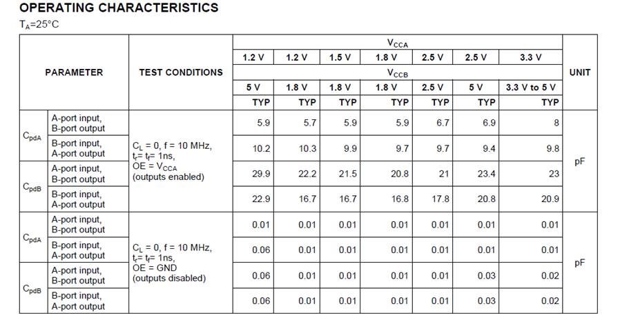
We would like to know how to Measure CPDA or CPDB?

Because we use TXS0108E on SMBUS DATA/SMUBS CLK, the level is +1.8V transfer to +3.3V M.2 wifi
For now we saw the SMBUS DATA couldn't low when we connect some module M.2 wifi.

The phenomenon will effect the system couldn't turn on system.

So, we think because some M.2 wifi CPDA or CPDB are over spec
Could you share experience for us?

Thanks!!

  • Hi Shu-Cheng,

    Cpd is the equivalent power dissipation capacitance used for power calculation in CMOS circuits. There is a detailed application report on the subject here: CMOS Power Consumption and Cpd Calculation

    The LSF0108 is not a CMOS device, and thus does not have an associated Cpd.

    If you would like to learn more about how the LSF0108 works, there is a detailed video series that we recently released available here: The Logic Minute

    Also, there are several application notes written on the subject, available here: LSF0108 Technical Documents

    If you need further assistance, please let me know.

  • Hi Sirs,

    Thanks for your reply.

    Actually we still confuse why some M.2 wifi card if connect TXS0108EPWR , the SMBUS DATA will couldn't to pull low.

    Do you have any experience on this phenomenon before? is possible cause on cpd??

    Or, have any restrict on use TXS0108EPWR ??

  • Hi Shu-Cheng,

    I'm not sure what you mean by "couldn't pull to low" -- were the drivers incapable of driving the signal below Vcc, or could they just not get all the way to 0V?

    The TXS family operates very similarly to the LSF family. There are added features to TXS, but essentially they have the same internal structure.

    The video "Down Translation with the LSF Family" explains around 1:08 how the device acts when it is in the low state. You can see that current is sinking from the output side into the driver side, and that will cause a voltage increase at the driver -- ie it is normal for the driver not to be able to get to 0V exactly. If it is exhibiting a large voltage when it should be 0V, then it is likely that too much current is sinking into the driver, and the circuit will likely have to be adjusted to fix the issue.