This thread has been locked.

If you have a related question, please click the "Ask a related question" button in the top right corner. The newly created question will be automatically linked to this question.

LSF0102: About the pull-up resistor value & About Vref

Part Number: LSF0102

Hello Team,

I have two questions below.

1) When looking at "9.2.1.2.2 Pull-up Resistor Sizing" in the datasheet, Rpu seems to be usable if it is 341Ω or more.
    Is there any problem using 10kΩ for Rpu ?

2) When Vref_A=3.3V and Vref_B=OE=0V, is there damage to the device ? No problem ?
    Usually we use Vref_A=3.3V and Vref_B=OE=5V, sometimes there is not supply of 5V power.

Best regards,
Kato

  • Hi Kato-san,

    1) When looking at "9.2.1.2.2 Pull-up Resistor Sizing" in the datasheet, Rpu seems to be usable if it is 341Ω or more.

       Is there any problem using 10kΩ for Rpu ?

    The pull-up size should be chosen based on the driver's current sinking capability, the parasitic capacitance on the line, and the desired data rate.

    There is a detailed explanation in this video: training.ti.com/TLM-LSF-Up

    2) When Vref_A=3.3V and Vref_B=OE=0V, is there damage to the device ? No problem ?

       Usually we use Vref_A=3.3V and Vref_B=OE=5V, sometimes there is not supply of 5V power.

    No, however Vref_B and OE should be tied to a 200kohm resistor and then to 5V, not connected directly to 5V.  Please see the video on biasing the LSF for a detailed explanation: training.ti.com/TLM-LSF-Bias

  • Hello Emrys-san,

    1) The output is open drain! I understood. I decide resistor value by data speed and sink current.

        However, I have one question.

        In the data sheet the following is stated.


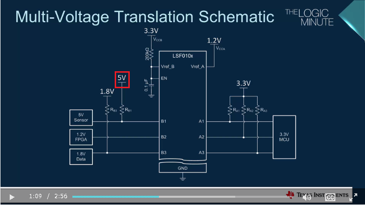
      The video "1.7 Multi-voltage Translation with the LSF Family" is as follows.


      Is there no problem if Vpu becomes larger than Vref_B ?

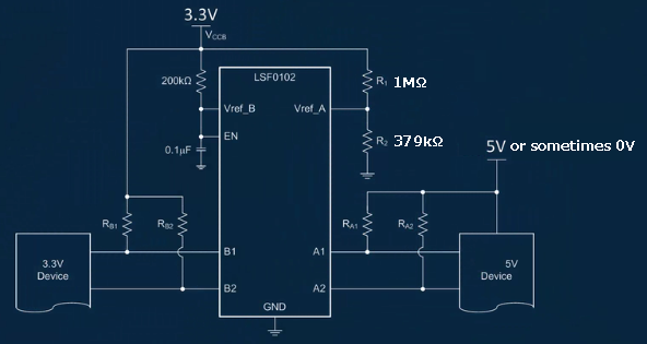
    2) I know to connect to Vref_B via 200kΩ. I want to know are the following.

           Is there any problem when Vref_B is 0V from time to time? Is there damage to the device?

      If it is NG that Vref_B becomes 0V, is it better to configure a single supply as follows?


    Best regards,

    Kato

  • Hi Kato-san,
    I believe that whoever wrote the application section was making a recommendation of VrefB as the maximum voltage for their application, but it is not a requirement for the LSF series of devices. The absolute maximum ratings table shows that each I/O can be between -0.5 to 7V regardless of the supply values, and the recommended operating conditions table shows 0 to 5V on all I/O pins to be safe.

    Vpu can definitely be larger than both supplies.

    Forcing the VrefB pin to 0V will not cause any damage to the device, and is actually how we recommend disabling the device (see the video on the Enable pin for details).
  • Hello Emrys-san,

    Please tell me how to disable it.

    Is it required to 0V with an open drain device to disable it?

    Is there no problem by setting Vccb to 0V?

    Best regards,

    Kato

  • Hi Kato-san,
    The left hand approach is the typical method for disabling the device because usually the power rails remain on.

    The device can also be disabled as you ahve described. Applying 0V to Vccb will very quickly result in a negative VGS across the bias FET, turning it off. The gate voltage for all channels will then be 0V.
  • Hello Emrys-san,

    It is the last question.

    If the direction of the signal is unidirectional, it does not need a pull-up resistor for input, right?

    Is it only necessary to have a pull-up resistor on the output?

    Best regards,

    Kato

  • If the transmitter is open-drain, then a pull-up is required. Otherwise, a pull-up is not required.

    A pull-up is always required for up-translation, on the higher-voltage side.

    A pull-up is not usually required for down-translation.