This thread has been locked.

If you have a related question, please click the "Ask a related question" button in the top right corner. The newly created question will be automatically linked to this question.

ISO7720: Emissions Reduction

Part Number: ISO7720
Other Parts Discussed in Thread: ISO7420, STRIKE

Hi,

Customer has two questions below.
Could you answer me, please?

Q1:How fast is the carrier frequecy?
Q2:How much is the range of spread spectrum by Emissions Reduction function?

Customer has a issue at noise insertion test.
It is that voltage waveform is not same between input and output.
He wants to know to consider this issue.
Signal is about 100bps.

Best regards,
Shimizu

  • Hi Shimizu,

    Have you tried the testing with ISO7720 device? Is noise insertion test failing on iSO7720 device also?
    Could you please share a few additional details like schematic and test results (waveforms)?

    Regards,
    Anand Reghunathan
  • Hi Anand,

    Customer tried only ISO7420 about noise insertion test.
    Customer wants to consider whether this issue occur with ISO7720 or not.

    In addition, Customer is considering the mechanism of issue at ISO7420 now.
    This issue has been resolved by adding LPF of input and capacitor of power line at ISO7420.

    Best regards,
    Shimizu
  • Hi Shimizu,

    As Anand mentioned, ISO7420 is an older generation device and ISO7720 is our latest digital isolator family.

    ISO7720 being more robust is not expected to cause an issue.  

    Regards

    Tejas

  • Hi Tejas,

    My customer tried ISO7720F. But this issue occurred.
    Customer tested IEC 61000-4-5.

    Could you advice me about this, please?
    ADUM120N and Si8620BC-B-IS didn't have this issue.

    Best regards,
    Shimizu
  • Hi Shimizu,

    Could you please give few more details about the failure?
    What issue has occurred? Did ISO7720F fail IEC-61000-4-5?
    What level of IEC-61000-4-5 did customer test? (Voltage level)

    Could you also describe the nature of failure? What has gone wrong in the device post stress? Higher ICC or device functionality?

    Thanks.

    Regards,
    Anand Reghunathan

  • Hi Anand,

    Thank you for your reply.
    I answer below.

    >Could you please give few more details about the failure?
    >What issue has occurred? Did ISO7720F fail IEC-61000-4-5?
    ->Customer system is 400W power conditioner.
       ISO7720F is used to isolate IGBT driver.
       When customer tests IEC-61000-4-5, IGBT was disrupted.
      Customer thinks this cause is the shoot through by turning on High side FET and Low side FET at same time.

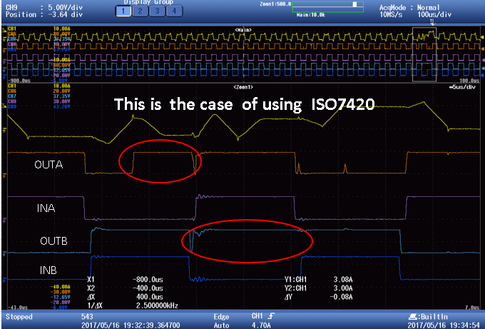
      Before, Customer had used ISO7420. At this time, When customer tested IEC-61000-4-5, IGBT was disrupted.  
      This cause is incorrect operation of ISO7420.
      Below picture is the waveform at ISO7420 issue.

    >What level of IEC-61000-4-5 did customer test? (Voltage level)
    ->2kV

    >Could you also describe the nature of failure?
    ->I still can't do it now.
       I requested the waveform at ISO7720F.
       Customer thinks the cause of IGBT destruction is incorrect operation of ISO7720F.

    >What has gone wrong in the device post stress? Higher ICC or device functionality?
    ->When customer tests IEC-61000-4-5, this issue occur.

    Best regards,
    Shimizu

  • Hi Shimizu,

    Is the strike being done on the VCC1 side of the board with Protective Earth connected on VCC2 side of the board?
    What is the yellow waveform shown in above figure?

    There is a possibility that the VCC of ISO7720F is seeing too much variation during the surge strike and the device is being turned off because of this. This happens only if the decoupling capacitors are not placed close enough to the devices or if the decaps are connected to the device through vias and are not connected directly to the device.
    If this happens for ISO7720F, the outputs of the device should go to zero which will NOT turn on both the IGBTs. However, if there are probes placed onto the output pins to measure such an event, the surge energy could couple through the probes and make the both the IGBTs turn ON causing a shoot through.

    My recommendation:
    1) If possible could you please share layout and schematic of the board? (only the ISO part along with all the decaps is sufficient). This is very important as we can debug if its the above issue by looking through the layout.
    2) Please add a decoupling capacitor of 1uF soldered very close to the device (if possible on the pins of the device)
    3) During the test would it be possible to remove the probes from the input and output lines as they may be picking up radiated energy and turning on both the IGBTs.

    Try the test with point number 2 and 3 implemented and please do try and share the layout if possible.
    If necessary, we can continue this discussion over email.
    Thanks.

    Regards,
    Anand Reghunathan
  • Hi Anand,

    Thank you for your reply.
    This issue at ISO7720F occurred without using probes.

    I want to discuss more deeply about this issue.
    Could you send me E-mail, please?
    My E-mail address is "m-shimizu@fujiele.co.jp"

    Best regards,
    Shimizu