This thread has been locked.

If you have a related question, please click the "Ask a related question" button in the top right corner. The newly created question will be automatically linked to this question.

ISOW7841: VISO regulates at 7V if input voltage is not stable

Part Number: ISOW7841
Other Parts Discussed in Thread: ISO1541, TCAN1051, TPS2114A

Hello,

I have a circuit using three ISOW7841 to provide independently isolated interfaces. One of the circuits is shown below (the other two are identical as far as the power rails go).

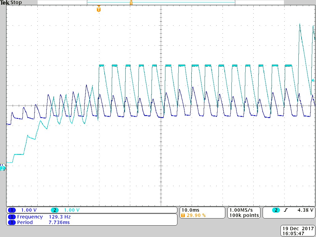
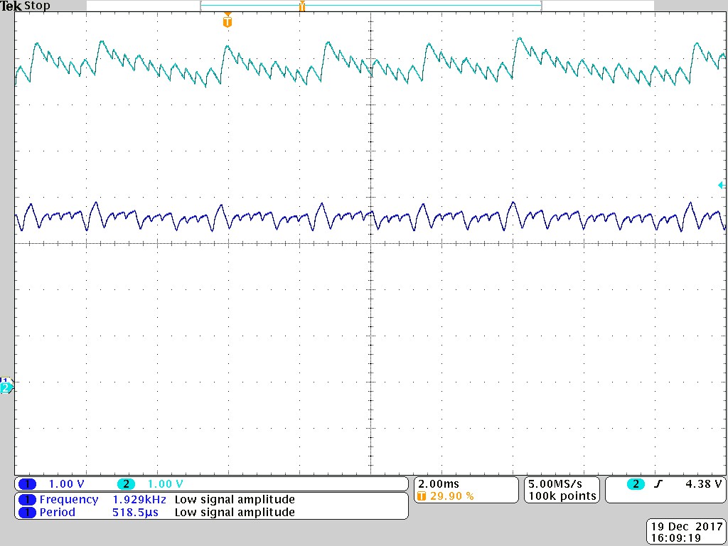
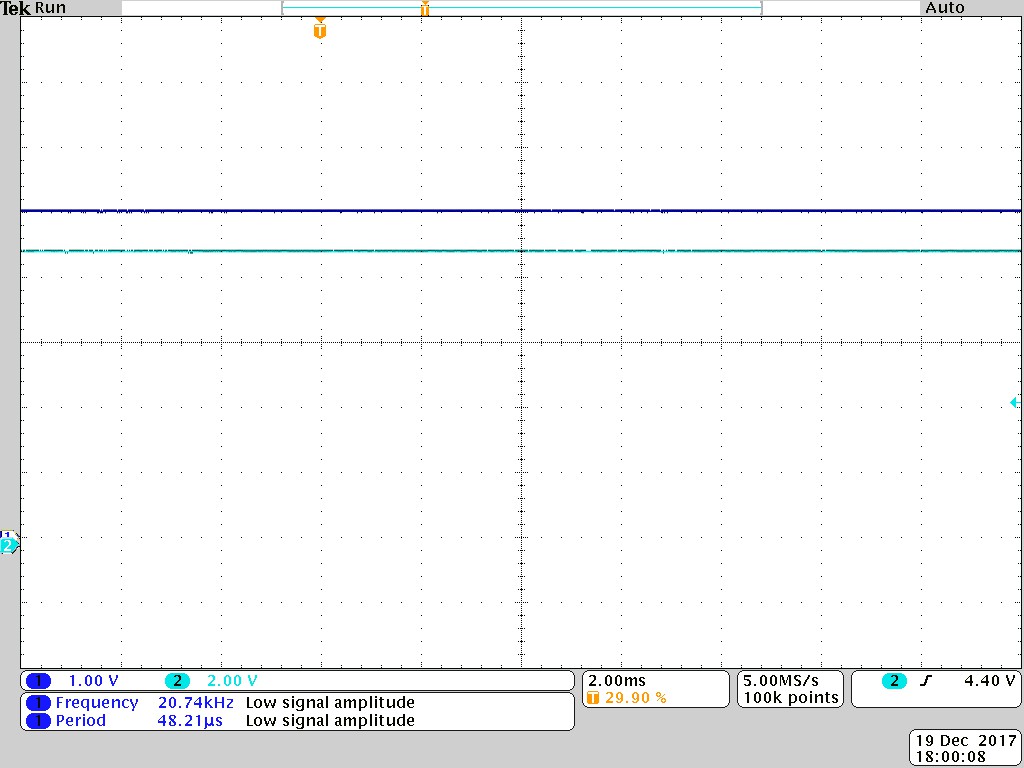
If the +5V_C rail starts cleanly then the ISOW7841 regulates nicely at +5.0V. However if +5V_C oscillates during startup (due to current limiting the input supply), then the ISOW7841 can end up regulating at +7.0V, even after the input has become stable. This could be the breakdown voltage of the 5V TVS on the output, or the ISOW7841 regulating at this voltage, but it is a very well regulated rail with almost no noise or ripple.

The only way to get the output voltage back down to +5.0V is to power cycle the circuit. The ISOW7841 is undamaged, and operates correctly after providing a clean startup.

I am working on some modifications to ensure that the input voltage is stable during the startup of the ISOW7841, but I would also like to know if there is anything else I can do to prevent the ISOW7841 from regulating at such a high voltage?

Thanks in advance,

Hayden Gray

  • Hi Hayden,

    Thanks for using E2E and for posting the schematic with your question. Always helps!
    I've reviewed your schematic with a colleague and nothing jumps out as a red-flag as such, so we may have to try out a few sanity-check experiments as options to find the root cause.

    Some options to consider below:

    1) Would it be possible to get a scope shot of the input, output supplies? Of particular interest would be the amount(amplitude) of oscillations, the region (on the input slope) where oscillations occur and the input supply ramp rate?


    2)Is it possible to double check the output voltage for ripple? Regardless of load current, we do expect between 70mV to 100mV ripple usually, even with the decoupling network shown. so the absence of ripple is a bit unusual.

    3)Can we remove the 5V TVS and see if the voltage remains at 7V or overshoots higher (possible)? May also change the regulation, ripple performance you have observed; but may be worth looking into.

    4)Do we see the same behavior if pin 10 (SEL)is left floating or grounded? This will make the device to regulate to a 3.3V setpoint and the intent is to force the internal circuit to take a different voltage target to see if it will still behave differently. This isn't intended as a fix , especially since you have a CAN transceiver hanging off the VISO side, just an experiment.

    5)Temporarily removing/bypassing the inductor L13 (47uH) and disconnecting all other loads on both Vcc1 and VISO may also be very useful for debug (especially if we can get to a temporary /equivalent setup where it boils down to just ISOW7841 and decoupling caps)

    Thank you,
    Abhi
  • Hi Abhi,

    Thanks for the comprehensive reply.

    I removed the 5V TVS (number 3) and did see some slight differences in performance. Below are all with the TVS removed.

    1) Below is a screen shot of the startup under severe current limited condition. Dark blue is the input voltage that you can see is getting high enough to start the three parallel ISOW7841, but the rail drops as they all sink current, hit the UVLO level and recovers, causing the oscillation. The ISOW7841 is doing what I would expect in this situation until the last 10ms of this scan, where the voltage spikes to 7V rather than the 5V from earlier.

    As the current limit is increased, we then see the input voltage rise enough that we aren't hitting the UVLO any more. So the ISOW7841 is now trying to regulate at 7V as shown below:

    Once the input voltage and input current were allowed to increase enough that the 5V rail could stabilize properly, the following output was observed. Note that the scale of the output had to increase as we are now regulating at exactly 9.0V!

    Is it suspicious that the device only regulates at exact odd voltages?

    2) I can't explain the lack of ripple either, like in the last picture. When operating normally, the ripple is quite obvious (although small) at this same scale.

    4) Floated pin 10 and the device regulates at 3.3V correctly when given enough current. It does seem better behaved, as I haven't yet seen the voltage go over 3.3V, unlike in 5V mode where I can consistently get higher voltages.

    5) Shorting out the 47uH inductor doesn't change the behavior. I also removed the supply from the other two ISOW7841 devices, and the device under test was more stable, but I can still get it to fault. I believe it was harder to reach the fault point because the upstream devices weren't going into current limiting mode as easily with only one device pulling current.

    Regards,

    Hayden

  • Hi Hayden,

    Thank you for sharing additional details.

    1) I wonder if the periodic entries & exits into/out of UVLO (due to heavy inrush current or load draw) on the input supply and combined with the internal soft -start circuit is causing the feedback loop to get affected and eventually move out of regulation . Your observations in #5 may support this - but we'll need to check some more.

    Do you have a heavy load and do you have any estimates on this? Also, are the decoupling caps placed close to the DUT? (We generally recommend at leat 10uF + .1uF placed within 2mm of the DUT on both sides of the ISO barrier.)

    2) Ok.

    4) Thanks for trying this . this is interesting behavior. The UVLO trip points on both Vcc1 and Viso remain the same and don't change, but the available output current (and therefore the loading on the input supply) changes, which may have more to do with the behavior seen.

    5) This may also be pointing towards a load current dependency.

    I have reached out to the designers also and will report back. Thank you.
  • Hi Abhi,

    1) Since this is happening during startup, and I have test code in the microprocessors, there is no comms taking place. Therefore the load is only a CAN transceiver in bus recessive mode (TJA1051: 2.5 - 10mA), an I2C based power monitoring chip (ISL28023: <1.5mA), an I2C isolator (ISO1541: 1.9 - 3.5mA) and whatever the ISOW7841 is using on the secondary side, so approximately 6 - 15mA.

    I initially had an LED on the secondary side drawing about 3mA in case I needed to add any additional load for stability, but this is currently not fitted.

    The caps are very close to the pins (the closest 0603 is 0.5mm away). We also use an 8-layer board with 0.1mm spacing between power and ground planes, so we get a huge inter-plane capacitance (hundreds of pF at virtually no inductance).

    In the meantime I have done a lot of additional experimentation. The end result is that if I put a 5.1V zener on the VISO rail (instead of the 5V TVS), the ISOW7841 doesn't get the opportunity to get out of regulation.

    It never tries to get to 7V or 9V, but regulates nicely at 5V once the input has stabilized. In addition to this I have also improved the startup of the downstream regulator, so that the ISOW7841 should not see such a nasty input voltage to begin with.

    Regards,

    Hayden

  • Hi Hayden,

    Thank you for the clarifications on #1. Good to know about this and the Zener diode working well in clamping the output. If I get any additional inputs from our development team I will post it here.

    Regards,

    Abhi

  • Hi Hayden,
    Happy new year!

    Just wanted to let you know that we are still doing additional analysis on this to see if we can avoid the Zener if possible. Is the setup as described previously working to your satisfaction?

    Is it possible to share the total system current limit you have allocated on the Vcc1 side ? Should we assume it is uniformly allocated across all 3 ISOW units ? I know we'd discussed about the initial current limits and then increasing them - was wondering if you could possibly share those values please?

    Thanks,
    Abhi

    PS: Slightly different topic but wanted to follow-up for completeness. You'd mentioned the TJA1051 using 2.5mA - 10mA in bus recessive state. If you'd like to cut that down to 1.5mA(typ) - 2.5mA (max) , you may be interested in the TCAN1051 as well [has a set of other useful benefits that could be of interest].
  • Hi Abhi,

    Happy New Year to you as well, I am back after a nice 3 weeks away, I hope you were able to have a bit of a break from work too.

    We are happy with the performance of the ISOW7841 when the zener diode is added to the output. We always use a TVS on every power rail (including internal isolated ones), so using a zener instead is not much of an issue.

    The current limit for the VCC1 side is set to 750mA nominal (about 600mA minimum) by a TPS2114A with a 333R ILIM resistor, and all three ISOW are in parallel. There is not any individual current limiting. There is also an LDO on the rail that draws 115mA for a +3.3V rail for a micro and other logic and sensors.

    I had tried a 1A nominal current limit during experiments, but it didn't appear to make much difference as then we start running into upstream current limits instead.

    Thanks for the suggestion of the TCAN1051, the HV varient looks like it would work nicely. We didn't have many options a couple of years ago when choosing a new CAN driver, as we use +48V power in the same cable, so were looking for at least 70V for bus fault tolerance. Now there are lots of options.

    Kind regards,

    Hayden