This thread has been locked.

If you have a related question, please click the "Ask a related question" button in the top right corner. The newly created question will be automatically linked to this question.

ISO1050: CAN bus 30M @ 1Mbps question.

Part Number: ISO1050
Other Parts Discussed in Thread: ISO1042

Hello.

We use ISO1050 for CAN bus application got 30M @ 1Mbps question.

Please kindly let me know why R1 = 120 Ohm / R2 = 120 Ohm is not work. And R1 = 60 Ohm / R2 = Open is Work.

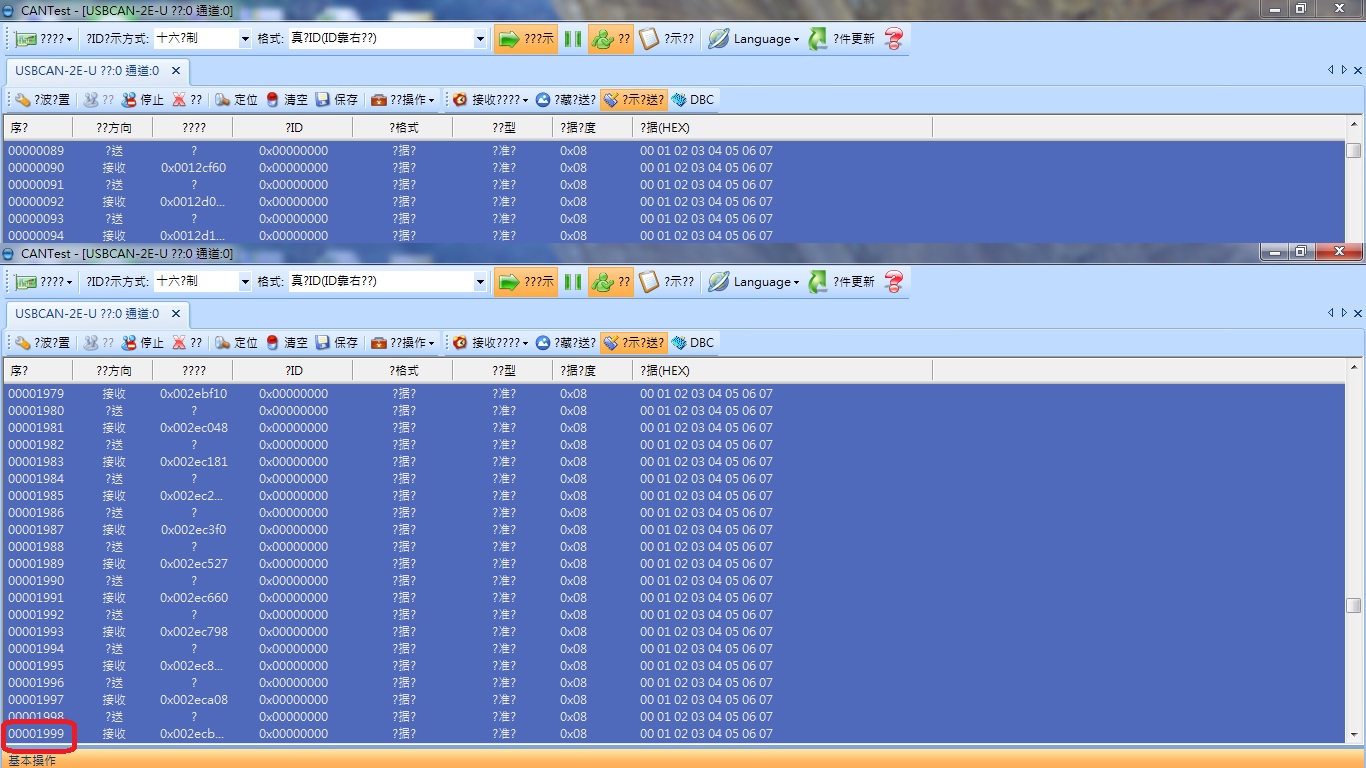
The test condition is transmissions 1000 times. CAN bus SPEC termination resistors is R1/R2 = 120 Ohm or not?

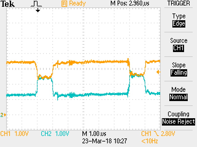
R1 = 120 Ohm / R2 = 120 Ohm @ 1Mbps test fail. CH1 and CH2 is CANH and CANL

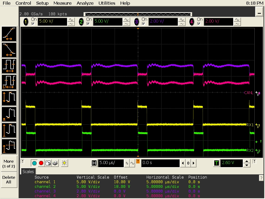
R1 = 100 Ohm / R2 = 100 Ohm @ 1Mbps test fail. CH1 is ISO1050 Rx. CH3 and CH2 is CANH and CANL.

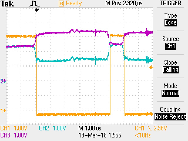
R1 = 60 Ohm / R2 = Open @ 1Mbps test Pass. CH1 is ISO1050 Rx. CH3 and CH2 is CANH and CANL.

  • Hi AJ Cheng,

    Thanks for using TI E2E forums.

    Yes the CAN standard (ISO11898-2) spec  is for an effective value of 60 ohms ( = two 120 ohm end-termination resistors ). Can you please elaborate on the pass/fail criteria further ?  I understand you are sending the data 1000 times  Are you seeing any bit errors reported? Or any specific criteria (time spec etc.) which is listed as a fail ? The reason I ask this is because the amplitude levels in the scope shots look OK to me.

    In Figure 1: (Scope shot): R1 = R2 = 120ohms;   in dominant CANH = ~3.4V, CANL =  1.2V and Vod = CANH - CANL = 2.2V; this is typical and healthy swing for a dominant bit. In recessive state, both CANH and CANL should be similar and they are around  2.4V. Again,  the amplitude levels are all within spec, so I am trying to better understand the fail classification. 

    Scope shot 2:  R1 = 100ohm, R2 = 100ohm;  Again I see healthy amplitude levels for both dominant and recessive states. Further, the RX output is faithfully following the CAN bus and is correctly reporting Recessive (RX = high; CANH - CANL = ~0) and Dominant (RX = low; CANH - CANL > 1.5V). so, just like above, any info here on why this is classified as a fail ?

    Scope shot 3:  R = 60ohms; R2= open;  this is  also similar to above.  Signal level is OK for both states (Dominant and Recessive) and RX output is following what it sees on the CAN bus.

    Below are a few things to double-check, this will help debug and understand the problem:

    1) Does your USBCAN-2E-U, already has built-in termination ? I looked this up online, some vendors ship with built in termination and others have external termination - depending on the model and vendor ( I versus II) .

    2) What is the capacitance (if any) connected to the CANH, CANL pins? This can be in the form of actual caps, or also through TVS diodes and/or chokes. A side question related to this is if the test passes at slower speeds, say 500kbps ? (for debug)

    3) What is the data payload you are sending ? I assume you are sending this via the USBCAN? I see 5 dominant bits followed by 1 recessive bit. ( this usually happens when you try to send a string of same bit ). Can you try with a 50% duty cycle just for debug?

    4) What is the TX input of the ISO1050 connected to?

    ===============

    Please let us know and we'd be happy to follow-up with you when we are back in the office on Monday

    Regards,

    Abhi

  • Dear Abhi.

    Thank you for your reply. Update on below for your question.

    1. I think our USBCAN-2E-U module not built-in termination. Because this module has two additional 120 Ohm resistors.

    2. USBCAN-2E-U setting to slower speed mode is not work. I think is slower speeds problem. 

    3. I can not change duty cycle from USBCAN-2E-U and please kindly reference the test results from USBCAN-2E-U tool.

    Test Fail

    Test Pass

    4. Please reference schematic on below.

  • Hi AJ Cheng,

    Thanks for your response and for providing the schematics. We have some additional thoughts - would appreciate your help in clarifying these so that we can debug this some more.

    1) I apologize that I couldn't fully understand the settings in the software screenshot since it is mainly in Chinese , but overall is it correct to say that the software settings are the same between pass and failing test, and the only difference is termination ?

    2) with R1 = R2 = 120ohms, and everything in the system connected, can you please measure the impedance between CANH and CANL lines and tell us what value you see ?

    3) the scope shots you shared : were they measured at the pins of the ISO1050? Would be useful to compare the waveforms at the USBCAN side and see if the signal shape is preserved or distorted ?

    4) Are B107, B108 Ferrite Beads with 600 ohm impedance @ 100MHz ? Can you please remove the beads and TVS (just for debug) and put R1 = R2 = 120ohms and repeat the test if possible ? This will provide useful information on timing.

    Thank you,
    Abhi
  • Dear Abhi.

    Thank you for your reply. Please kindly reference on below.  Thanks for kindly help~

    1. Yes.

    2. 57.9 Ohm

    3. ISO1050 side

    USBCAN side

    4. We have already removed B107 / B108 and D44.

  • Hi AJ,

    Thank you for your patience and for the data and - very helpful.
    ------------------------
    - If you measure 57.9ohms, there is no issue with double termination , so we can rule that out.
    - Software settings and speed- we may have to revisit this later. Let us hold for now.
    - Scope shots: The bit level amplitude and timing looks healthy, both at ISO1050 side and also on USBCAN side.
    -------------------------
    So perhaps some issue is going on at the __frame__ level ? To analyze this:
    (a) we will likely have to zoom out in the scope and try to get at least 29 bits of data, and see if there are any missed bits in the frame.
    (b) When we do the above, we may have to get two set of scope shots,:
    - TX, RX, CANH, CANL with 29 bits on ISO1050 side
    - same as above on the USBCAN side.

    Again, thank you for your patience as we work together to debug this issue.
    Best regards,
    Abhi
  • Dear Abhi.

    Good day. Can I ask another question about ISO1050 EVM schematic? Why is the EVM put 60 Ohm termination resistor. Thanks~

  • Dear AJ,

    In a real CAN network, we expect the two end  CAN nodes  to be terminated with 120 ohm resistor each to match the cable impedance. Two 120 ohms in parallel will give us an effective impedance of  60ohms.

    On an EVM , since we have only one node ( = one transceiver), we directly use the effective impedance of 60ohms as a standard load.

    This is also consistent with the CAN standard and CAN datasheets, where 60 ohms is used a standard value when measuring just one CAN transceiver.

    I hope this helps.

    Best regards,

    Abhi

  • Dear Abhi.

    Good day. We provide video record on below for you reference. Is it likely to be a matter of compatibility problem? If any suggestion please kindly let me know. Thanks~

    R1 = 120 Ohm / R2 = 120 : 0:03 second is start transmission and 0:19 second got fail.

    R1 = 100 Ohm / R2 = 100 : 0:04 second is start transmission and 0:06 second got fail.


  • Dear AJ,

    Thank you posting this. On Friday and today, we have been in email and phone discussions with our Field team there to look at this. I am re-posting some of that here for convenience.

    There is a possibility of the USB2CAN module doing something here, so compatibility could indeed be a factor. We saw the videos and in the beginning, the scope shot looks OK, but only later do we see the bits getting affected and moving around.  This may be due to interference, or even the software trying to do something in the middle of transmission. **if** this was a hardware issue, we would have seen ***all ** bits getting affected and not only some in the middle.

    Therefore, for simplicity of debug, we recommend trying this with two ISO1050 EVMs.   We tested and reconfirmed this in our lab -  two ISO1050s with one 120ohm resistor at each end were able to communicate without any issues. This was also verified in our lab today by Dan Kisling (thanks Dan). I am attaching the scopeshot here:


    When testing with two EVMs, it is good to start with a smaller cable length  (5m, 15m etc.) and also with slower speeds (250kbps, 500kbps etc).  After these tests  work smoothly, you can scale it to 1Mbps, 30m.

    Best regards,

    Abhi, 

  • Dear Abhi.

    Good day. In this case if only R1 = 60 Ohm / R2 = Open can fixed this issue. Can we use this method?

    If possible, please kindly help me to confirm if layout needs improvement. Thanks for help~

    CANH and CANL

    CANH and CANL

    Tx and Rx

    Tx and Rx

  • Dear AJ,

    Hi and good day to you as well.

    Generally, we don't see or recommend the use of single 60ohm resistors - unless the numbers of nodes are very small **and** the distance between them is also small. The simple reason for this is to control and minimize reflections from a long cable and for good signal integrity.

    We will be glad to help you with the layout, but to do that: we need the following info as well:
    1) System schematic
    2) How many nodes in total ? (1 node = 1 CAN transceiver + 1MCU)

    A schematic review/discussion is best handled over email and or a conference call. This is to protect your IP. Is it okay for me to contact you at the email address you have used for the my.ti account ?

    Best regards,
    abhi
  • Dear Abhi.
    Good day. Thank you for your reply and help.
    my.ti account email address is OK or you can provide your email address.
    I will provide those information for you and Thank you for always helping~~
  • Hi AJ,

    I will reach out over  to your email. Once we are done in email,  I will post a high-level summary here.

    Also, for completeness, I wanted to share an additional scope shot (courtesy Daniel Kisling; thanks Dan).

    This is with two ISO1050 EVMs, 120ohms on each side and separated by 20m cable with a lot of stubs (= unterminated sections) in between to deliberately make this a difficult test. Device 1 transmitting and listening and Device 2 listening. As you can see,  there is small noise (due to stubs), but despite this, the ISO1050 has no issues communicating.

    This addresses the termination side of the question as well as the cable length.

    Purple = CANH,

    Red/pink = CANL

    Yellow = RX1  (receiver output on device 1)

    Green = RX2  ( receiver output on device 2)

    This data leads us to believe that there may be a USB2CAN related issue or a software config issue.

    We can double confirm this when you can also test with two ISO1050s.

    Thank you. As mentioned I will reach out separately for schematic and layout review discussions. 

    abhi

  • Dear AJ, Gary

    1) Schematics reviewed - sent you feedback

    2) Answered all test/debug questions in your email.

    3) Video : sent you feedback over email. Essentially - appears to be error frames being sent in the middle. Maybe a controller config (software issue), because if this were to be a hardware issue, then you will see this in every few bits and not just in the middle.

    4) Layout: Hard to review like this in general (best done over a call , selecting layers , traces and components) but in general , we can recommend the following:

    • supply and ground planes are clean
    • Decoupling caps (100nF) is placed as closed to the device as possible, including paying attention to the VIAs between power  and ground planes. (Vcc1-Gnd1; Vcc2-Gnd2)
    • CANH and CANL lines/traces are roughly equal/symmetric
    • CANH, CANL lines are not routed next to high-speed switching lines from Micro (can cause interference).

    Doing the tests you plan to do with PCB, EVM and USB2CAN module is a good idea.

    Please let us know if this addressed all your questions. Do let us know how it goes with the customer.  If there is flexibility to use both ISO1050s or both ISO1042, that will be best of course.

    If USB2CAN **has** to be used, and if there are only 2 nodes to be used, *and* if extensive data testing shows shows good performance without any bit errors (with effective termination = 60ohm), then that termination setup can be acceptable as well. It is not the normally recommended solution but can be made to work.

    Best regards,

    Abhi