This thread has been locked.

If you have a related question, please click the "Ask a related question" button in the top right corner. The newly created question will be automatically linked to this question.

ISO35: Max voltage at A/B

Part Number: ISO35

Hi

I am trying to understand the effect, if any, of a common mode RF sinusoid applied to the receiver inputs.  It seems that the relevant parameter to look at is the -9V to 14V max pin voltage listed in table 7.1.  Is that a static parameter (i.e. damage will occur if >14V is applied to the pin indefinitely), or is there a time element associated with it?   Also, what is the expected failure mode for a voltage on the input pins that exceed the datasheet range (-9V to 14V) for the A/B inputs?  For reference, here is the circuit:  


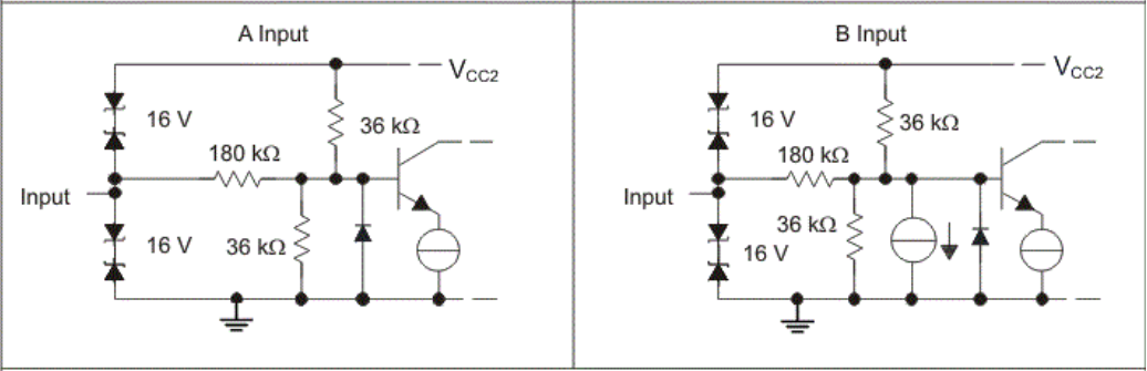
In particular, I'm am curious about the negative limit.  If -10V, for example, is put on the Input, I'd expect to see the diode near the base of the BJT to forward bias, but the resistance in that path is quite high, so I wouldn't expect much current to flow (~52uA), and therefore I do not expect the power dissipated in the diode to exceed a few hundred microwatts.  So, I doubt that is the failure mode.  I think -10V shouldn't be enough to cause the 16V protection circuit to turn-on either...although, I guess the voltage between VCC2 and Input is close to about 16V if VCC2 is at 6V. 

Any details you could share would be greatly appreciated.  Thanks!

Paul

  • Hi Paul,

    To answer your first question. Any voltage that appears on a pin that exceeds the absolute maximum ratings will permanently damage the device (even if it is only for a short time). But continuous operation beyond the recommended operating conditions are not recommended as it may end up affecting the reliability of the device.
    On a side note, none of the datasheet parameters are guaranteed if the voltage applied is beyond the recommended operating conditions (even if it does not exceed the abs maximum ratings of the device).

    I agree that the IO circuit shared in datasheet doesn't give a clear idea on how the failure occurs. I'll get back to you on that with some additional clarification.

    Regards,
    Anand Reghunathan
  • Hi Paul,

    Sorry for the delay in getting back to you on this.

    Regarding the mode of failure when the negative voltage is being applied. Whenever we have input common mode that exceeds the supply, we often use internal attenuation that compresses the [signal + Vcm] into a smaller value which is safe for the low voltage internal circuits of the IC. If the input exceeds a certain value, then the ESD cells can break and also some internal junctions can become unintentionally forward biased and dump current when they shouldn’t, these can in turn result in device getting damaged.

    Could you please also give me a few details on how the common mode signal will look like with the RF sinusoid superimposed on it? (Amplitude, Frequency etc).
    Depending on the level of noise injected.
    If it violates the abs max conditions (-9V to 14V) this could cause permanent device damage.
    If this noise is within the abs max conditions but are still violating the recommended operating conditions (-7V to 12V) then the device may not get permanently damaged but communication/functionality of the part will be lost temporarily when the RF noise rises to those levels.

    Regards,
    Anand Reghunathan