This thread has been locked.

If you have a related question, please click the "Ask a related question" button in the top right corner. The newly created question will be automatically linked to this question.

ISO7740: ISO7740 transmission signal loss problem

Part Number: ISO7740

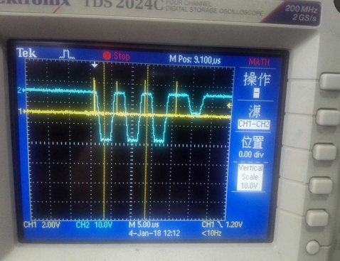
The TI ISO7740 isolator does not work properly, loses the signal, and the silionlab si8645ba can work properly. Please help analyze the reason

Note: the transmission is the pulse signal, the signal rate: 30MHz, the GND_F voltage variation amplitude -40V--0V, frequency: 50kHz
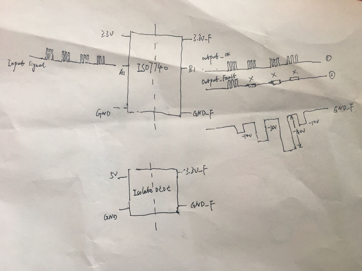
  • Hi Bunney,

    Could you please let me know what is the pulse width of the 30MHz signal that is being applied?
    ISO7740 has a requirement for the pulse width to be at least 10ns whereas for Si8645 it is 5ns from its datasheet. This looks to me like one possible reason for data loss. Let me know, thanks.

    Regards,
    Koteshwar Rao
  • Hi Koteshwar,

    The pulse width >10ns, 

    Look at the schematic diagram of my drawing. The first set of signals can be transmitted completely, but the three groups of signals are missing.

    This problem should not be related to the pulse width.

    Is it related to the negative voltage disturbance superimposed on the GND_F floating ground?

  • Hi Bunney,

    Regarding the possibility of minimum pulse width violation, if the pulse width is marginally just over 10ns then it is possible that some pulse pass through and some might not.

    The negative voltage disturbance doesn't seem to be a problem, still I would like to understand more about it. Could you please let me know what is the slew rate of this negative voltage disturbance?

    Can you please tell me what is the decap values used for VCC1 & VCC2?
    Can you tell us if this issue has been observed on only one device / PCB or is it being observed on multiple devices / PCBs?
    It would also be useful if you can share us schematic and any test waveform observed? Thanks.


    Regards,
    Koteshwar Rao
  • the pulse width>20ns,

    the slew rate of this negative voltage disturbance: 50V/us

    Vcc1: 3.3V Vcc2: 3.3V

    it is being observed on multiple devices / PCBs

  • Hi Bunney,

    Koteshwar also wanted to know the values of decoupling caps. Are they mounted at the right places? See section 9.2.2 of datasheet.

    Can you post a two channel scope plot showing simultaneously the signal and ground noise?

    Kai
  • the values of decoupling caps is 0.1uF.

    two channel scope plot:Ch 1:signal  Ch 2:GND_F

    The right signal wave :

    The Wrong signal wave :

  • Thanks for the nice scope plots!

    Interesting, the pulse train becomes damaged, even when there's no GND noise signal at all.

    Hhm, have you checked the situation with a fresh ISO7740?

    Kai