This thread has been locked.

If you have a related question, please click the "Ask a related question" button in the top right corner. The newly created question will be automatically linked to this question.

ISO1050: RX didn't receive data issue

Part Number: ISO1050

Hi Team,

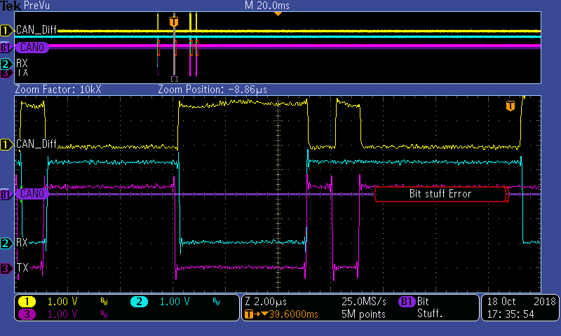
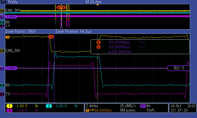
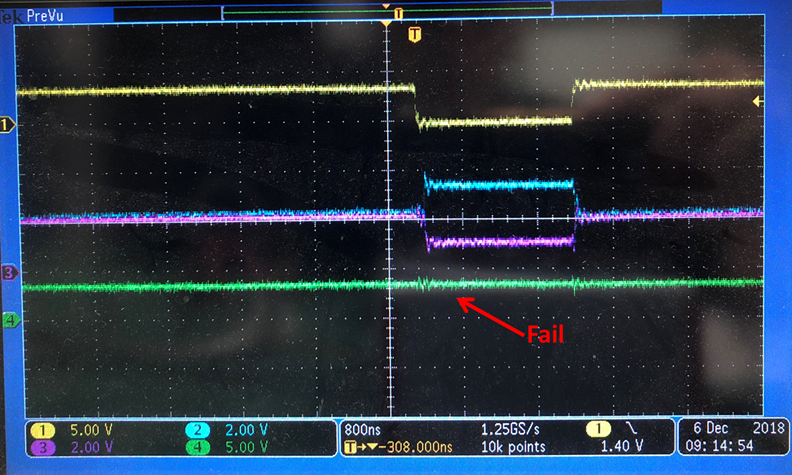
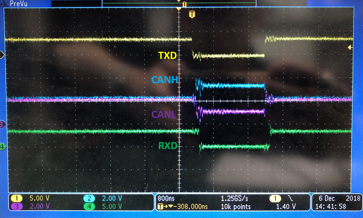
My customer using ISO1050 discover a issue that RX didn't change when TX sent data.

Please see schematic and waveform as below.

Have you seen similar case?

  • Hi Tiffany,

    I'm sorry to hear that you are having an issue with the ISO1050. I think this is the first time I have seen a case like this, but perhaps I do not have enough details yet. I have a few follow up questions for you:

    Is this error repeatable?

    Does this happen during startup?

    Best regards, 

    Dan

  • Hi Dan,
    This error can be easily reproduced and it's not just happened at startup.
    I have tried to use PCAN transmitting TX at period 1sec repeatedly and expect for receiving RX from client.
    Some expected RX didn't received from client which is correspond to the waveform shown.
    And i also find that when i heat up this ISO1050 (using hair dryer ), the fail disappear.
    But using Refrigerant, the fail phenomenon actually become worse.

  • Hi Zhe Ming,

    Thank you for providing additional details.

    What is the horizontal time division on the scope set to in the scope shot you have sent? I am trying to determine the pulse width of the bit that the ISO1050 did not transmit.

    Since it is easy to reproduce, I would like to try to recreate this in our labs. Are there any other details you can provide to best re-create this issue? I have the following details from your schematic: Vcc1 = 3.3V, Vcc2 = 5.0V, 120 Ohm termination on CAN bus, issue gets worse with cold temperatures.

    Best regards,
    Dan
  • Hi Dan:

    From the previous attached figure, the room factor is 2kX, so the time division should be 2k*10us=20ms (Sorry for all measured figures are zoom in setting).

    And an interest thing can be noticed that at normal condition, the CAN TX will lead RX about 120ns. But before "bit stuff error" happened, the CAN RX rise at the same time with CAN TX.

    As you know, the pin space are wide that can exclude the SMD impact. But  i will still take the photograph and X-Ray to examine at this aspect.

    Figure 1: When Stuffing error happened, you can found previous TX RX vary at the same time

    Figure 2: Zoom in Figure 1

    Figure 3: At normal condition, TX lead RX by 12X ns

    12X ns fits the IC spec.

    I trigger this fault by CAN decoder and the trigger condition is "Stuffing error".

    Could you guess the reason why TX and RX can rise at the same time ? I think this is a breakthrough point.

    Thanks for your support : )

  • Hi Zhe Ming,

    Yes after closer inspection it is very suspicious that TX and RX happen simultaneously. The ISO1050 is not capable of doing this by itself.

    How are CAN_TX and CAN_RX connected to the microcontroller? One thing I think would be worth trying is to disconnect CAN_RX from the micro and get similar scope shots as you obtained before.

    Best regards,
    Dan

  • Hi Dan:

    As previous schematic shows, CAN0_RX & CAN0_TX connect to MCU  CAN port directly.

    After taking the photograph, there have no found related SMD problem.

    And yes, after taking X-Ray, i will implement SWAP test of ISO1050 and this can exclude the MCU side doubt.

    By the way, previous experiment that when temp drop, the fail phenomenon happened apparently .

    At that time, i only use refrigerant toward ISO1050(only small region).

    The distance between MCU and ISO1050 is about 18cm, so the temp vary can't directly influence the CAN port of MCU.

    This make me more sure that this problem come with ISO1050.

    Ya, i think it's right that at normal ISO1050, RX and TX shouldn't rise at the same time.

    But if this ISO1050 actually failed and can reproduce this problem.

    Is there any possibility can produce this problem for reviewing ISO1050 internal design and manufacture process ?

    Bgds

    Jimmy

  • Hi Jimmy,

    Yes please continue with the experiments described. Looking further at the failure scope shot you sent earlier: RX is actually predicting the future a bit. Signal should propagate TX --> CAN --> RX. It looks like RX is actually switching before the CAN bus transitions.

    Is it possible the input of your micro controller (CAN_RX) is somehow driving the line? Perhaps the drive strength of RX on ISO1050 is stronger when the device is heated and so it is able to overcome the micro, but during cold or room temp the ISO1050 is not able to.

    Best regards,
    Dan
  • Hi Jimmy,
    I haven't heard from you in a few days. Were you able to resolve the RX issue?
    Best regards,
    Dan
  • Hi Dan:

    I will swap ISO1050 tomorrow, thanks.

  • Hi Dan:

    After swap ISO1050, the phenomenon come up with ISO1050 IC.

    And i also take X-Ray photograph of this IC, it seems bonding wires are normal.

    Later i will send this sample to TI (Taiwan) for further analysis.

    Thanks

    Jimmy 

  • Hi Jimmy,
    Were you able to test with RX not connected to the microcontroller as we discussed?
    Best regards,
    Dan
  • Hi Dan:

    No, because i don't have jumper on TX and RX trace thus i have to cut off trace to verify this.

    (By the way, FW will change the activity if the MCU didn't receive RX data that may confuse us)

    But i have done the swap process that on another PCBA the TX RX have no error from CAN log.

    And later this ISO1050 may put on TI EVM board to double check this issue.

  • Hi Jimmy,
    Any updates on this? Do you still need further support?
    Best regards,
    Dan
  • Hi Dan,

    We plan to put the ISO1050 IC with issue on EVM to verify it's function.
    We are waiting to receive the ISO1050 EVM. Will update the testing result once we finish the test.
    Thanks.
  • Hi Tiffany and Jimmy,
    Just wanted to check in, has the EVM arrived?
    Best regards,
    Dan
  • Hi Dan:

    Yes. We found this issue also can be reproduced by TI EVM. 

    I have filled document for requiring your TI support

    Thanks.

    Following waveforms are measured at EVM by another FAE.

    Normal:

    Jimmy

    Bgds

  • Dear Dan,

    This is TI distributor FAE, CK.

    I captured the fail waveform on ISO1050EVM.

    Please see the figures as below.

    You can see the RXD sometimes will not change after TXD transition from high to low.

    Fail unit:

    Fail unit (zoom in):

    Normal unit:

    Normal unit (zoom in):

    The testing methodology is referred to ISO1050EVM user guide.

    I just use a function generator to stimulate TXD, then measure the waveform of CANH, CANL, and RXD.

    By the way, I found that the failure rate will increase if I decrease the data rate.

    When TXD running at 1Mbps, this fail phenomenon will disappear.

    But if TXD runs under 600Kbps, you can see the failure occured frequently.

  • Jimmy, CK,

    Thank you for the additional details. I am having trouble replicating the failure on our end. Could you help provide me with more information on how this experiment was conducted?

    This is what I just tested in the lab on the EVM:

    Vcc1: 5V, Vcc2: 5V

    TX (from signal generator): 0-5V 150kHz square wave with 75% duty cycle. Monitored on scope in yellow.

    CANH / CANL: Monitored on scope in green / purple. Not connected to any other nodes on network.

    RX: Monitored on scope in pink.Not connected to anything else. 

    This is what I saw on the scope. I tried to match your scopeshot. 

    I then setup the trigger to only trigger when TX was LOW and RX was HIGH for greater than 500ns. This should then trigger whenever RX fails to follow TX. This was run for several minutes, but the scope did not trigger. So I was unable to find an instance where the ISO1050 created a bit error. 

    Best regards, 

    Dan

  • Dear Dan,

    Yes, only the suspect IC has this fail phenomenon. And the suspect IC is on my hand now.

    There is no bit error If I measure the normal one. The waveform is the same as yours. You can see the figure I posted before.

    All of your setting is the same as mine, only one is different, I set VCC1=3.3V and TXD=0-3.3V. But I think it doesn't matter.

    Thank you very much.

  • Hi CK,
    Okay I understand now - only the suspect IC has this failure phenomenon.
    Tiffany and I are now communicating offline to discuss this issue further.
    Thanks!
    Dan
  • Hi all,
    I have received the EVM with the failing unit in Dallas. I have been able to replicate the failure. I am in contact with Tiffany and will continue the discussion over email for now, but will post the conclusions here when they are found.
    Best regards,
    Dan