This thread has been locked.

If you have a related question, please click the "Ask a related question" button in the top right corner. The newly created question will be automatically linked to this question.

ISOW7842: ISOW7842 Viso damage

Part Number: ISOW7842
Other Parts Discussed in Thread: ISO7842,

Dear all,

we are using the ISO7842 in one of our products to control an isolated switch as depicted in the picture below. "control signal"  has logic high voltage level for a maximum of 1.5s and therefore, the switch closes (load: 1A) and then reopens again. On some of our PCBs we observe the following problem:

"control signal" is activated (high) for 1.5s, the switch closes and then reopens again. But after 1.5s, the ISOW7842 heats up caused by a short circuit of Viso/GNDiso (it is definitely the chip itself, after removing it from the PCB the short circuit on the PCB also disappears). In general, the ISOW7842 is not damaged the first time when "control signal" is activated, it needs some trials until the short circuit appears. Is there a mistake in our circuit (maybe the high impedance connection of primary and isolated ground) or a known issue with the isolated supply?

Kind regards.

Sebastian Reichhold

  • Hi Sebastian, and welcome to TI's E2E forums!

    From my understanding, this ISOW7842 only supplies current for the T600-2 gate through IC601-2 without driving the load connected across it - is this correct? 1A is too much current for the ISOW7842 to supply.

    Shorts from a device's supply to ground are typically from overvoltage or ESD stresses although it has been uncommon for the ISOW. Are you aware of transients affecting any of the ISOW7842 device's pins? A timing breakdown of when exactly the device shorts and what is happening in the system will also be helpful.

    Please let me know the information you have! I will await your response.


    Thank you,
    Manuel Chavez
  • Hi Manuel,

    your understanding is correct, the ISOW7842 only supplies the T600-2 gate through IC601-2 (by the way, the 1A through the switch are driven from an external power supply). I will do some measurements and hope to get the moment the ISOW7842 is destroyed. Maybe it will take some time to reproduce but I will let you know as soon as possible.

    Kind regards.

    Sebastian Reichhold

  • Hi Manuel,

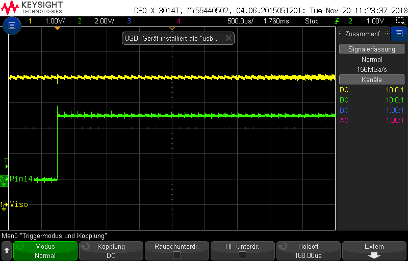
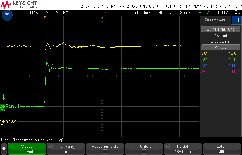
    here are some screenshots of the measurement. Keep in mind that the device is still working (I did more than 50 tests) which means I do not have a timing breakdown of the failure.

    Nevertheless, channel 1 (yellow, 1V/div) is Viso and channel 2 (green, 2V/div) is pin 14, the signal that controlls the gate driver. At first view, Viso voltage looks OK. What about pin 14 signal (There is a short spike up to 6V but this could also be caused by my setup because I had to use wires of 10cm length to contact the measuring point)?

    Beside this, I will contact our manufacturer whether something special happend to the ISOW7842 parts during the manufacturing process? Are there any special recommendations about the handling of the ISOW7842?

    Kind regards.

    Sebastian Reichhold

  • Hi Manuel,

    some more information:

    1. The parts were baked (48h @ 120°C) before use and the maximum temperature during the soldering process was 230°C. So moisture and soldering temperature (according to datasheet, 260°C is the peak temperature) can be excluded as the damaged parts cause, correct?

    2. There is another PCB with one damaged ISOW7842 where the circuit on the isolated side (gate driver and FET) was never used. The ISOW7842 was broken before the FET switched 1A load for the first time.

    3. I did a test where 4 circuits were tested 3000 times (each circuit switched 1A 3000 times). I could not reproduce a broken ISOW7842, they are still working.

    I think (because of information 2. and 3.) the circuit on the isolated side is not the reason for the broken ISOW7842. The only thing (I found out up to now) that is common to all damaged ISOW7842 is their part marking which is

    79A1LHT

    ISOW7842F

    G4

    Is it possible that we got bad components (for whatever reason)?

    Kind regards.

    Sebastian Reichhold

  • Hi Sebastian,

    Thanks for sharing additional details, they are very useful to understand your how ISOW7842F is used in your system and how it is being tested. Please find below my inputs regarding the information you have shared in your previous post.

    1. Do you know if the temperature test (48h @ 120C) was done with device powered or unpowered? If powered, do you know what was output voltage and current? In either case, the 48h temperature testing at 120C shouldn't be an issue for ISOW7842 but please do share the above requested for me to reconfirm.

    2. Could you please share more details regarding when and how exactly did you see the failure of ISOW7842? Did you notice failure during power-up? Any more details you can share about this particular test?

    3. Understood, thanks for running these tests.

    We do not expect the parts to be damaged as all the parts go through extensive testing in the factory and only those parts that comply to the datasheet go out of the factory. I will still check if anybody else had any issues with ISOW devices from the codes that you have received.

    To further understand the issue, could you please share me the below information?

    a. I couldn't make out if the switch T600-2 is used as a low-side switch or a high-side switch?

    b. Is the switch used for static ON/OFF control or is it going to be switched ON/OFF at a particular rate?

    c. Do you know what would be the peak current requirement by IC601-2 for it to be able to drive the switch?

    If you are further testing ISOW to find out if there are any more failures, please do make sure you monitor VISO to be able to find out what causes damage to VISO. Thanks.


    Regards,
    Koteshwar Rao
  • Sebastian,

    Thanks for the oscilloscope images and every piece of information about this system. Regarding your waveforms post, digital output ripple is expected to vary based on load, so 1V may not be problematic. Is this waveform repeated if a different channel is used, say B (pins 4 & 13)?

    You'd mentioned that all of the affected devices have the same part marking - this is also helpful information.

    I appreciate your responses and want to welcome Koteshwar, my colleague, to this thread. My responses will be delayed until next week due to the Thanksgiving holiday.


    Happy Thanksgiving!

    Best,
    Manuel Chavez
  • Hi Koteshwar, hi Manuel,

    to answer your questions:

    1. The temperature test (baking) was done with the devices unpowered.

    2. Unfortunately, I do not have more details when and how exactly the failure appears. All I can say is that some devices were damaged during the test (control the switch for 1A load) and some devices were already damaged before the test. As mentioned above, I tried to reproduce the failure by testing 4 devices 3000 times, but all devices are still working.

    a. Switch T600-2 is used as lowside switch.

    b. The switch is used for "nearly static on/off" control. Nearly means, the switch is turned on (= conducting) for 1.5s seconds and then turned off again. During the 3000 times test, the switch was turned on every 10s for 1.5s.

    c. Assuming the gate of switch T600-2 is completely discharged, the peak current is about 5V/5Ohm = 1A. I know 1A is too much for ISOW7842 output but as there is nearly no voltage breakdown of Viso (see screenshot above) I reason the current is drawn from the bulk capacitors C600-2, C606-2 and C608-2 (the gate capacity of T600-2 is much less than the capacity of the bulk capacitors).

    It is difficult to test a different channel, e.g. B (pins 4 & 13) because it is hardwired to GND. I would have to rip up some via/track of my PCB. But the waveform is nearly the same when tested with another device.

    Kind regards.

    Sebastian Reichhold

  • Koteshwar, Manuel,

    I have additional system information and we will discuss this offline.
    Come back to you asap.

    Regards, Bernd
  • Hi Sebastian, Bernd,

    For the completeness of this E2E post, I would like to update the latest status of our discussion and close this thread.

    From our discussion, further testing of ISOW7842 didn't produce any failures and we concluded that it is possible the samples are damaged due to handling either at the distributor or at the EMS.

    I am closing this E2E post now, if there is any further update please feel free to create a new E2E post or reach out to the TI representative. Thanks.


    Regards,
    Koteshwar Rao