This thread has been locked.

If you have a related question, please click the "Ask a related question" button in the top right corner. The newly created question will be automatically linked to this question.

amc1301

Other Parts Discussed in Thread: AMC1301, OPA320, ISO224, AMC1311, AMC1311EVM, TLV704, SN6501

hii alex 

how are u doing 

i want to use the amc1301 to sense a power ac line that has an amplitude ranges from 0 to 700 volts with frequency of 60 hz 

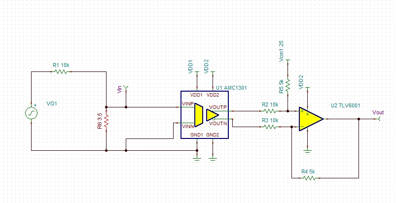
as i see i need to use resistor divider  network at the input of the AMC1301 so when the ac line is 700v the max amplitude at VINP pin is 250mV .(i connect the VINN to ground ) 

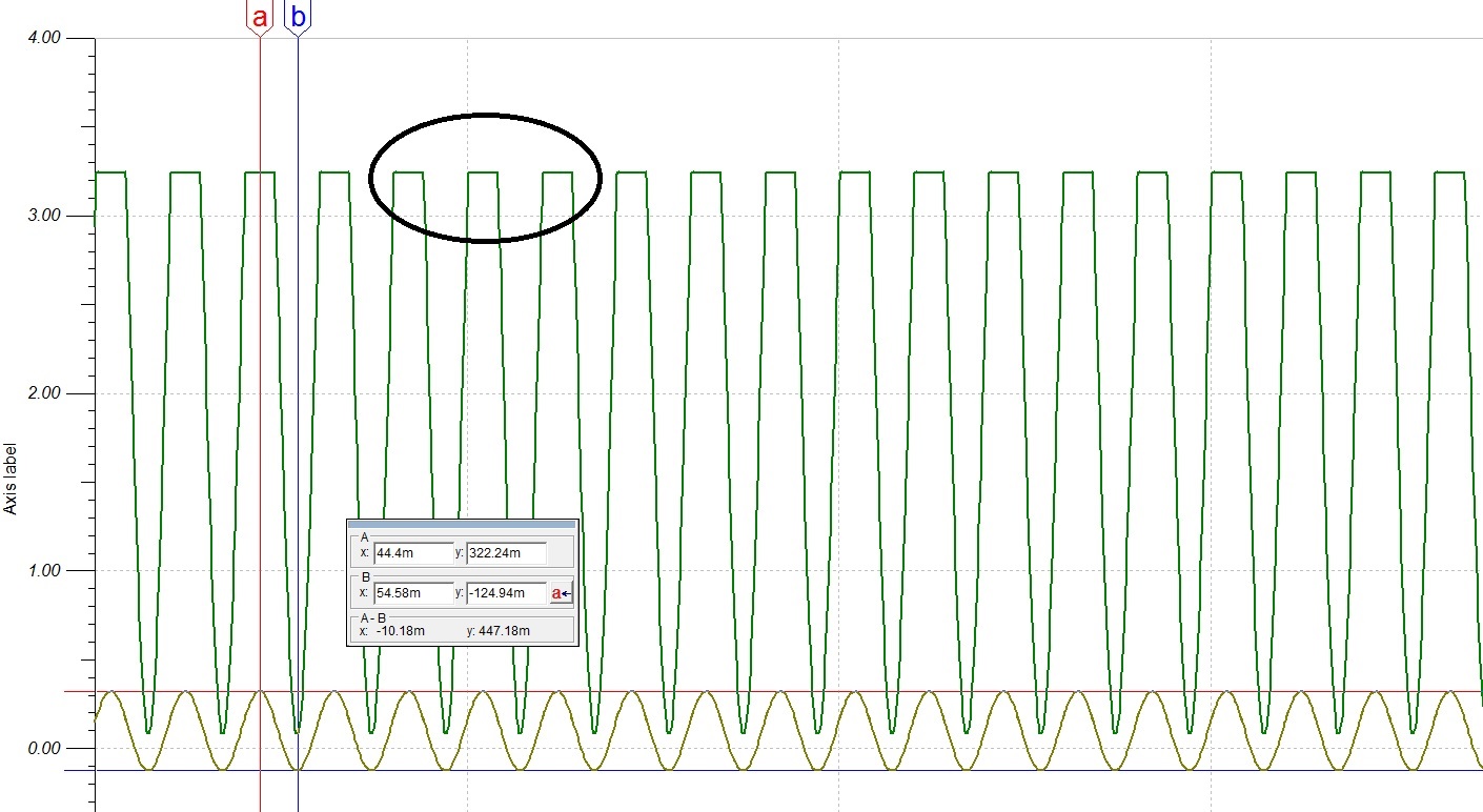
but i have a problem with this design and my problem is when the power line amplitude reduces down to 100 volts or less i get very low input voltage at VINP about 5mV and its not very big swing at the input of the isolation amplifier .

do have any recommendation of how to sense high ac voltage like in my case 

i can solve this issue by connecting a different resistor network  so when the amplitude voltage gets down to 100volts i start to use another resistor divider network that give me 250mV at the input of the amc1301

but i want to see if you have another approach  for sensing an voltage with an amplitude of 700 AC volts using the amc1301 

  • Hello Aied,

    Thanks for your post! I am well and I hope the same to you.

    Can you post a schematic that shows your resistor divider network?

    The voltage should be proportional, so if 700V on the AC line corresponds to 250mV, then 100V on the AC line should be 35mV; not 5mV.

    Having a second resistor network is an interesting idea but I believe that it may lead to problems if it doesn't switch back correctly - either physically or in the code.
  • hii alex 

    good morning 

    yes you are right 100v  is equal to 35mv 

    the resistor network is 10K and 3.5ohm

    do you have a recommendation for other resistors values?

    and yes i intend to change the resistor network by hardware but i wanted to see if there is another idea for doing this measurement?


  • hii alex
    one more question the phase of the output signal does it have any drift relatively to input phase ?
    cause i consider the output phase to have the same phase as the input ?
  • Hi Aied,

    Thank you! I hope you have a good afternoon.

    These resistor values are not safe for dropping 700Vac - the voltage will be dissipated as heat and I doubt that these resistors could handle such a drop. When you choose the resistors to use here, make sure you look at their thermal ratings to ensure that they can handle the heat that will be generated. Please be safe when working with voltages this high!

    Take a look at this thread, I believe they are performing a measurement very similar to yours: e2e.ti.com/.../2281751

    And this TIDesign for reference: www.ti.com/.../tidubx1b.pdf

    This post should answer your second question: e2e.ti.com/.../743968

    Let me know when you change your schematic and if you have any other questions!
  • hii alex

    thanks for your help 

    i did a simulation using TINA for the reinforced amc1301 circuit that is in tidubx1b.pdf 

    for sensing the DC bus input voltage.

    i wanted to sense a 566 AC volts with 50 hz frequency 

    and i got the following results

    the peak value of the input signal is 322mv

    and the minimum value is -124mv

    and  the output of the opamp was clamped at the maximum and not a full sin wave

    i expected to see +/- 250mv at the input  and a full sine wave at the output i tried of biasing the input but the output was still clamped ,do you have any idea why?  how to correct the circuit in order to utilize the range of the 250mv input  566volt main line sense1.TSC

    i attached the Tina design 


  • the output of the op-amp320 was clipped at 3.24
    the output of the opamp320 is feed into the mcu ADC
  • hii alex ,how are you doing 

    did you see my question?

  • Hi Aied,

    Apologies for the delay in response, it was a Holiday in the US last week.

    Are you calculating the 322mV peak and -124mV minimum using the DC transfer characteristic?

    Using Analysis -> AC Analysis -> Calculate Nodal Voltages, I am seeing 224mV Amplitude and 186mVrms on the input.

    The output of the OPA320 should be 0 to 3V, correct?
  • hii alex 

    hope you had a good refreshing holiday :)

    i attached a screen shot of the simulation 

    as you can see the input is with 322mv max amplitude and -124mv   when i take the deference between this values  its about 340mv which is much higher than 250mv input swing of the device this is one problem

    and the second one is this input sine wave is not centered around 0v    

    from the resistor divider network at the input should be 250mv once there is 566v at the input line .

    and the out put op the opamp is clipped at the max peak of the output wave  , and yes the output should be between 0 and 3v cause i feed it to my ADC    e output of the opamp should be between 0 to 3v cause i feed to my adc 

  • hii i also attached the schematic that shows the resistor network that i use at the input 

    by voltage division if there is 566 VAC by phase i should sense 250mv 

    and this is not happening in the simulation the amplitude  as i mentioned above 322mv and -124mv

    and i suspect that is whats causing the clipping at the output on the op amp.  

  • 566volt main line sense1_AS.TSC

    Hello Aied,

    I believe the error is due to the AMC1301 bias current model. The AMC1301 has a typcal output bias current of 15uA on both VINP and VINN for a total of 30uA output bias current. I am unable to verify how much bias current the simulation model produces. If you look at the file I attached, the DC offset is mostly removed when I scale down the input resistance by a factor of 128. This is impractical for a real application due to thermal concerns of the resistors, but I thought it would help to at least simulate the OPA320 stage.

    I also added an additional resistor to the VINN trace to help minimize the DC offset. This configuration can be seen in figure 52. of the datasheet. Look at equation 1 in section 10.2.2.1 Design Requirements to see the gain error equation. Since the input impedance of the AMC1301 is low, when a comparably sized resistor is used for the shunt then it creates an additional resistor divider. Try to get the shunt resistance as low as possible if you are going to use the AMC1301 for voltage sensing. Considering an isolated amplifier for voltage sensing (AMC1311, ISO224) is another route to go as well if you are unable to perform system calibrations.

    I made a few changes to the OPA320 stage. I added VCM of 1.5V connected to the positive input terminal of the OPA320 which sets the common mode to 1.5V (halfway between 0 and 3V ADC input range) and changed the values of the feedback resistors to fit the fullscale range.  There seems to be some clipping on the negative side of the output swing (85.74mV) that is most likely due to the model. The OPA320 datasheet specifies less than 50mV for all cases of "Voltage output swing from both rails", so I am not sure why I am seeing 86mV. I do not support the OPA320, so I cannot speak to how accurate it's model is. Perhaps you can post to the amplifier forum and they will have an answer.

  • hii alex thanks for your reply

    i saw your modification on the circuit 

    it looks like the answer to my voltage sensing is using the AMC1311 that you suggested to me :)

    i will try it , and if i will have questions i will get back to you , again thanks for your help.


  • Happy to help Aied!

    Have a good rest of your day.
  • hii alex , hope you are doing will

    alex i have a question 

    in the  AMC1311EVM board guide  there is a segment talking about isolation between the two VDD rails of the AMC1311 using push-pull driver witha center taped transformer  

    in my design i need about 5 components of AMC1311 for voltage measuring , and i don't think that for every AMC1311 amplifier i need to build supply isolation circuit that is on figure 3 of 

    http://www.ti.com/lit/ug/slau745/slau745.pdf

    and my question is how many amc1311 isolation amplifiers i can connect to supply circuit that is Shown in figure 3?

  • Hello Aied,

    Thanks! I hope you are well too!

    This depends on a few things, including what voltage you will be supplying. Looking at the SN6501 datasheet - it can supply up to 350mA on a 5V supply or 150mA on a 3.3V supply. The TLV704 LDO can handle up to 150mA on the  high side output. Then looking at the AMC1311 datasheet, the maximum current that will be drawn on VDD1 is 9.7mA.

    This means that you could have up to 15 devices (150mA/9.7mA) using the recommended circuit. However this is for a perfect system and does not take losses and inefficiencies into account. I think 5 AMC1311 devices should be fine.

    The attached app note may be helpful as well:SN6501_HV.pdf

  • hii alex 

    thanks for your reply 

    i get you , i will proceed in my design with 5 amc components 

    if i will have more questions i will get back to you 

  • hii alex

    i guess there is no ending to my questions :)

    as i told you i am using the AMC 1311 to measure voltage of an ac industrial phase as you know there are three phases R S T and the return N and the actual ground.

    lets say i want to measure the voltage deference between R and N , i am confused where to connect the GND1 of the VDD1 rail of the AMC1311
    do i connect it to N line?

    and lets say i want to measure also the deference between the N and the G in a another AMC1311 do i in this case connect the GND1 to GROUND of the power line ?
  • Hi Aied,

    I made a mistake in my previous post, I was not considering that you would be measuring different phases - I was only thinking in terms of current consumption. Since you are measuring different phases the measurement potential will be greatly different between the devices and therefor you will not be able to use the same power supply for your 5 AMC devices. The transformer on the EVM is single phase, which means you would need 1 per phase, a minimum of 3. If you use a 3phase transformer, then you would be able to use one tap per phase.

    Take a look at this TIDesign, I think it will help illustrate my point: www.ti.com/.../tidu755.pdf
  • hii alex 

    thanks for your reply

    yes i can see in figure 6 of tidu755.pdf that each phase has a different  power supplies for the amc1311.

    but i want to ask about the ground in each side of the AMC1311 isolation amplifier 

    in figure 6 of f tidu755.pdf  there is a voltage divider in the bottom of the design for measuring voltage

    and i have two questions:

    1- the ground of the VDD1 power supply on the left of the AMC beside the motor (ground of  the TPS7A3001 side ), is it connected to the neutral phase pf the motors ?

    2- the ground on VDD2 on the right of the AMC (ground of  the SN6501DBV) , is it connected to the ground of the SitaraTM AM437x IDK ?? cause the output of the AMC goes to an ADC so that means that the ground of the ADC on SitaraTM AM437x IDK is connected to the ground of the SN6501DBV , am i right?

    i am asking cause i am confused about the ground layers of each side of the AMC and my design is similar to the design presented in the   tidu755.pdf 


  • Hi Aied,

    It should not be connected to the neutral, as it's voltage can change based upon phase loading. This could cause the circuit to violate the power supply limitations of the device based on the characteristics table. For additional examples of how to connect the circuit, take a look at figure 49. and 52. in the datasheet and make sure that the power supply limitations will not be violated.

    The low side GND can be connected to the Sitara GND, but it really depends on your design and if you have one or two GNDs. For the two GND system an analog and digital gnd is used, then the two GNDs can be connected using a zero ohm resistor.
  • hii alex thanks can you send me a link to the datasheet that shows figure 49. and 52 so i can see hoe to connect the ground on the high side ??

  • hii alex i looked at the data sheet of AMC1311 and i can see what you mean

    in figure 49 GND1 of the AMC1311 IS connected to -Vbas of the motor driver

    but in my case i want to use the AMC 1311 to measure the voltage difference between a phase to a neutral (for example measuring the voltage difference between a phase and neutral of 220VAC wallsocket ) and my question is where i connect the GND1 of the hige side in my design ?
    all my my confusion is about the ground on the high side :)

    lets say the input to my circuit comes is phase and neutral from the wall socket how can use the AMC1311 to mesure the diffrence voltage ?
  • Hi Aied,

    GND1 will connect to whatever you are measuring with respect to. If you will be measuring phase to neutral, then GND1 will connect to the neutral.

    This post may help: e2e.ti.com/.../383424
  • HII ALEX 

    thanks for your reply , i think this sums up my questions for now :)

    i will proceed in my design .

    hope every thing goes smoothly