This thread has been locked.

If you have a related question, please click the "Ask a related question" button in the top right corner. The newly created question will be automatically linked to this question.

ISO7721: ISO7721 Part

Part Number: ISO7721
Other Parts Discussed in Thread: ISO7741EVM

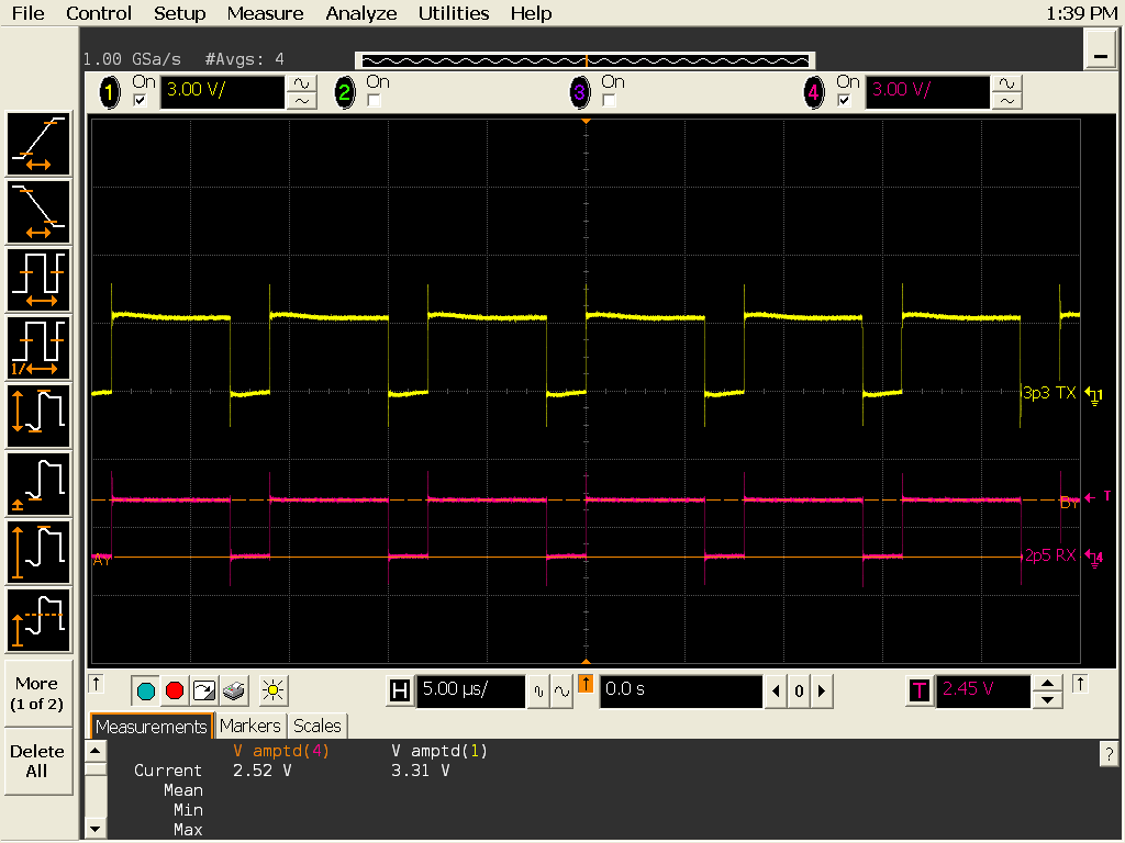
Hello.  I am a first time user using the ISO7721FQDRQ1 part.  This is the 8 pin part.  I am getting no output.  I have a 20KHz, 3.3V square wave going into pin 3.  Pin 1 is connected to the 3.3V supply. Pin 4 is connected is connected to the 3.3V ground.  Pin 8 is connected to the 2.5V supply and pin 5 is connected to the 2.5V ground.  I have tried pulling the output up (10K) and also pulling it down to 2.5V ground and still nothing on the output.  Any help would be greatly appreciated!

Mark

  • Hi Mark,
    Thanks for asking your question on E2E.
    It sounds to me like you have everything hooked up correctly.
    Are you using the ISO77xxD-EVM? www.ti.com/.../slau695.pdf
    What are you using to generate the 20kHz, 3.3V square wave?
    Best regards,
    Dan
  • I am using an Agilent 33250 to produce the square wave. I also use the ISO7720FQDQ1 part on my board and it works just fine.  I disconnected VCCo (pin 8, 2.5V) to the VCCi (pin1, 3.3V) on the ISO7721 chip and I was able to see the signal at the output.  The data sheet is not real clear on what the differential voltage can be between the VCCi and VCCo pins.  In all of the electrical characteristic section VCC1 and VCC2 are the same voltage.  What is the  differential voltage between the 2 supply pins?

    So the bottom line is that the chips that have the same voltage on VCCi and VCCo work just fine. The chips that have the different voltages on VCCi and VCCo do not work.  Any ideas?

    Thanks--Mark

  • Hey Mark,
    Vcc1 and Vcc2 are independent of each other, so this should not be an issue for the device. I'm wondering if the 2.5V supply is seen as a full 2.5V at the Vcc2 input of the device, as it only works down to 2.25V so any more than 10% droop could cause an issue. Do you have the flexibility to try 2.7V on Vcc2 just as a quick experiment?
    Also to clarify, the signal is input into pin 3 - so it's referenced to GND1, correct? And when you are monitoring pin 6 you are referencing that to GND2?
    Best regards,
    Dan
  • Hi Dan.  I did measure the voltage at the 2.5V side (VCCo) and was getting 2.54V.  I just tried your idea of raising the voltage to 2.7V.  I raised mine to 3V and the chip is now working.

    I did double checked the reference to ground with respect to the signal generator and the scope and it was correct.  I am convinced that there is something going on in the chip with respect to the VCCi and VCCo potential difference.  Perhaps you could check with the chip designer and find out what exactly the max potential between the two VCC are.

    Thanks--Mark 

  • Hey Mark,

    The maximum working isolation voltage for the ISO772x in the D package is 637VDC. This can be found in Section 6.6 Insulation Specifications in the ISO7721 datasheet

    I quickly recreated the setup you described in the labs here in Dallas on an ISO7741EVM (same architecture, just a different channel count device) and I did not have an issue with the two different voltage potentials. Vcc1 = 3.3V. Vcc2 = 2.5V. The scope is monitoring the signal incoming on side 1 (referenced to GND1) and the output on side 2 (referenced to GND2). You can see the RX signal is at a proper 2.5 volt amplitude (measured at the bottom of the screen). 

    Best regards, 

    Dan

  • Thanks Dan. I did not ask about what the isolation voltage is I am asking what is the maximum voltage potential between VCCin and VCCout?
    Is there someone you can ask?
    Thanks--Mark
  • Hi Mark,

    Sorry for the confusion. Please allow me to elaborate:

    The parameter that represents the maximum potential difference that the ISO7721D can have between any pins across the barrier is working isolation voltage.

    So the maximum potential difference that ISO7721D can have between any pin on Side1 (from pin1 to pin4) and any pin on Side2 (from pin5 to pin8) is termed working voltage. Since working voltage for ISO7721D is 637V DC, the maximum potential difference that ISO7721D can have between VCCO & VCCI is 637V DC and it will still work fine.

    With regards to how your test is setup, perhaps a connection diagram could help. This is how I tested it in the lab with Vcc1 = 3.3V and Vcc2 = 2.5V. The signal generator is referenced to GND1 with an amplitude of 3.3V and the scope is referenced to GND2. Is this representative of how your test setup looks?

    Please let me know if there is anything that is not clear and I would be happy to clarify. 

    Best regards, 

    Dan

  • Hi Mark,
    Hope you had a good holiday! Please let me know if you need any further assistance.
    Best regards,
    Dan
  • Hi Mark, all,

    Since this thread has been inactive for a couple of weeks, it will be closed. For additional comments or related questions, please feel free to create a new thread or ask a related question using the red or yellow buttons in the top right corner of this window.


    Thank you for posting to the E2E forums,

    Manuel Chavez
  • Hi Mark,

    In case the discussion above intentionally disregards isolation, the max potential difference between Vcc1 and Vcc2 = Vcc1(max) – Vcc2( min) = Vcc2(max) – Vcc1(min) = 5.5V – 2.25V = 2.75V. The two supplies are truly independent and isolated from one another.


    Thank you for your time,
    Manuel Chavez