This thread has been locked.

If you have a related question, please click the "Ask a related question" button in the top right corner. The newly created question will be automatically linked to this question.

SN6501-Q1: ISO voltage supply drawing more then queiscient spec.

Part Number: SN6501-Q1
Other Parts Discussed in Thread: SN6501

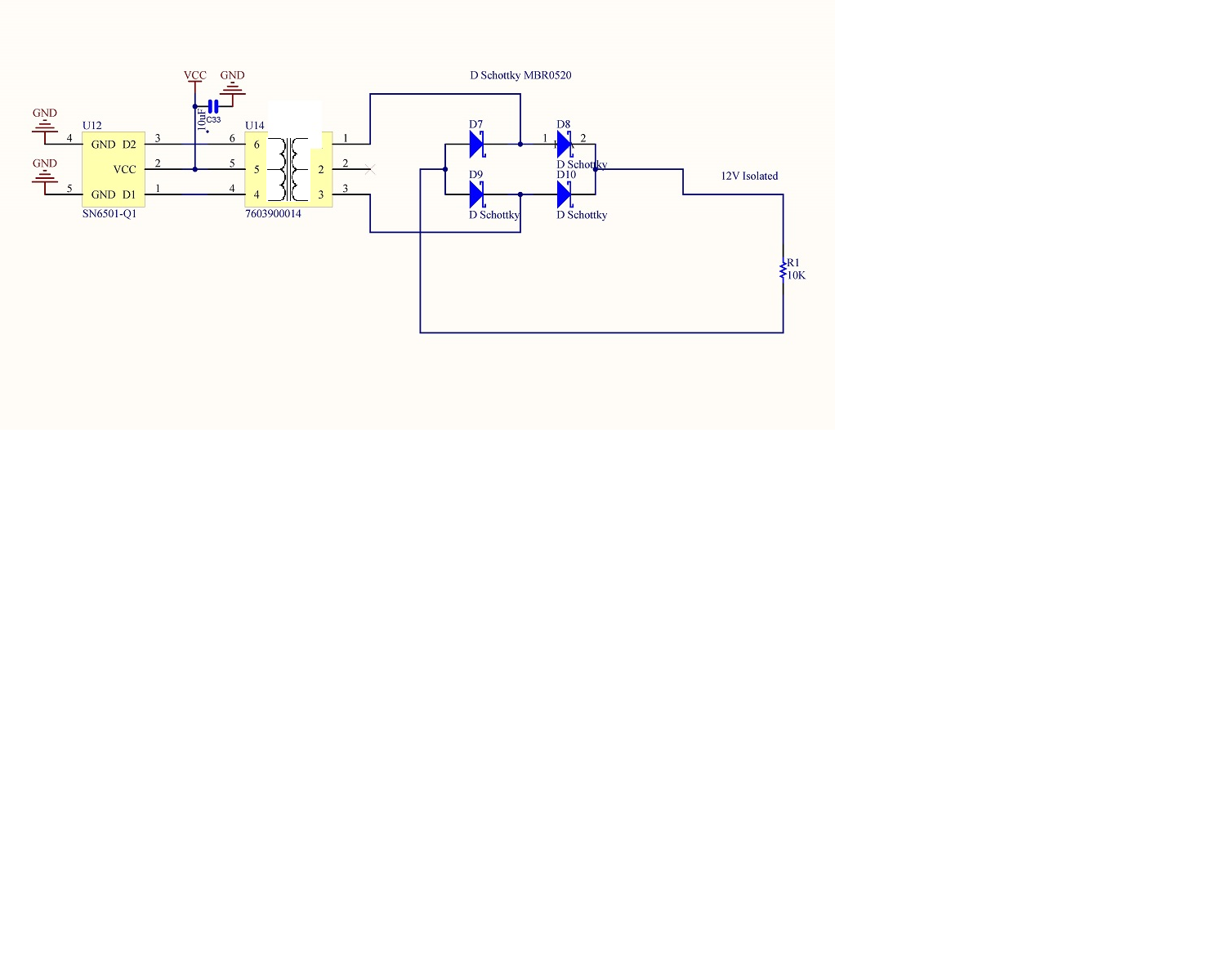
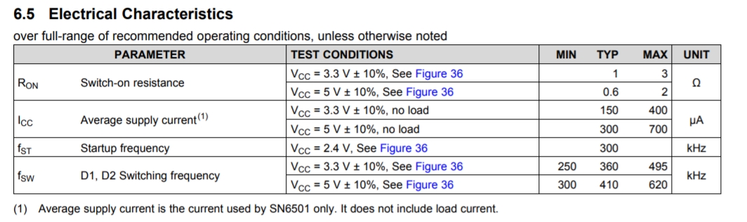
The data sheet for the SN6501 list the supply current @ ~300uA.  In the configuration below I would then expect to see about 1.5mA consumption (10k load  (1.2mA) plus supply current).  But I am measuring about 7mA.    I am assuming the load from the windings in the 7603900014 and the diodes are causing the additional current draw. 

The efficiency rating show about 85% based in voltage output and load current, therefore I would an additional 1mA @85% not 6mA.

Is there any way to get this circuit to function closer to a 2mA total draw?

  • Hi FJ,

    Thanks for using our E2E forums for your support needs,

    We'll try to address your question step-by-step.

    1) The typical quiescent current spec @ 5V input supply is indeed 300uA, however this is specified for no load condition and includes the part only [please see image below]. You are correct that the extra current you are seeing is because of the transformer and also some part from the load. Transformers do have some overhead in the sense that they need a minimum amount of current to cover for magnetizing current inside the core.

    2) Now the second part is the efficiency aspect. The 85% number is peak efficiency at high or full loads and measured with a standard full-wave rectifier circuit.

    At very light loads, looking at Figure 10, the efficiency can be between 10% to 20% [ the graph ideally needs to be zoomed in closer to look at an exact value].

    If we take this number, then the primary current =  [1.2mA (load current) X 1.3 (turns ratio)  / 0.1 (efficiency] + 0.3mA [quiescent current of 6501]. This comes to 15.9mA using 10% efficiency ; and 8.1mA using 20% efficiency.  So what you are seeing is within the bounds of our expected values.

    Getting to 2mA total on the input side with a 1.2mA output load current is unfortunately very tricky to be achieved at the moment with our current offerings. One (remote) possibility is to enquire with transformer vendors if a custom design can be done which requires very low magnetizing current, but we also have to keep an eye on what other trade-offs are involved.  In that context, can you please share more details of your end application?

    Regards,

    Abhi

    PS: Edited to fix datasheet image link

  • Thank you!