Other Parts Discussed in Thread: ISO1042
Hi Sirs,
Sorry to bother you.
We would like to know ISO7721
If VCCI and VCCO voltage and GND are the same
This thread has been locked.
If you have a related question, please click the "Ask a related question" button in the top right corner. The newly created question will be automatically linked to this question.
Hi Shu-Cheng,
This is no bother! Although the voltages Vcci, Vcco and GNDi, GNDo can be the same voltages connected together, this configuration will not have the effect of isolation.
In an isolation schematic, GNDi and GNDo should be separate ground planes with no connection to each other. This is also true of Vcci and Vcco: for isolation, they cannot be connected to each other. An example of how this looks on a PCB is shown below:
Isolation can be achieved in this design! It is a matter of isolating the power supplies and separating the GNDs. Will you like some guidance on how to do this?
Thank you for posting to E2E,
Manuel Chavez
Hi Shu-Cheng,
No problem! I apologize for the delay. I have some questions and comments for your points:
I hope this is a helpful response! Please do reply with any additional questions or concerns.
Thank you for your time,
Manuel Chavez
Hi Sirs,
Thanks for your reply.
At present, our termination resistors are expected to be implemented in the following two locations.
Please help me to confirm if there is any problem? thanks
Hi Sirs,
Update our board schematic as below
This board is the red part of the system block, could you help double check it? Any suggestion are welcome
Schematic:
system block
BCB Board Block Diagram
Hi Sirs,
Sorry for pushed, have any update on this topic?
Any suggest are welcome.
Thanks!!
Hi Shu-Cheng,
I apologize for the delay in my responses.
Regarding the post with termination resistors on June 14th, the location of these termination resistors is good if the LED Driver and BCM nodes are the longest nodes in the network. It seems like they are, but if the ATX 12 board has more cable than one of the other two nodes, the termination resistors should be in different places.
On the following question, both Digital Ground and ISO Ground are set up correctly. Only what is on the right side of the isolation barrier (which you have in the red box) should be connected to ISO Ground.
Thank you for including the block diagram! In the 55.pdf schematic, it will be beneficial to include a 10uF capacitor on pin 2 of the transformer (U32). Capacitors C304 - C307 are not critical, but of course you may leave these in.
I appreciate your patience with this response; please feel free to follow up with additional concerns of comments.
Thank you for your time,
Manuel Chavez
Hi Sirs,
Thanks for your reply.
About the 55.pdf schematic review, in addition to U32.Pin2 need to add a 10uF capacitor, others schematic looks good. Is it correct?
Hi Shu-Cheng,
Yes, the schematic from what is shown looks to be properly connected. As an additional note, please do ensure that the 3V3 and 4V0 power supplies are isolated from GND_ISO.
Are there additional questions I can help with?
Respectfully,
Manuel Chavez
Hi Sirs,
Thanks for your reply.
One more question,
We wonder if we need to do the impedance control and twist pair for the CAN Bus pair signals (CANH/CANL) on the interconnection cables?
Could you help to clarify? Thank!!
Hi Shu-Cheng,
Yes, feel free to use twisted pair for the CAN bus pair signals. The cables should have a nominal impedance of 120 Ohms to minimize reflections. Ensure you are minimizing cable lengths for stubs, which is what the cable for the ATX 12 board will be.
Can you please share the part numbers of C304 - C307 capacitors? I have looked for them inline without any results so far.
Thank you for your time,
Manuel Chavez
Hi Shu-Cheng,
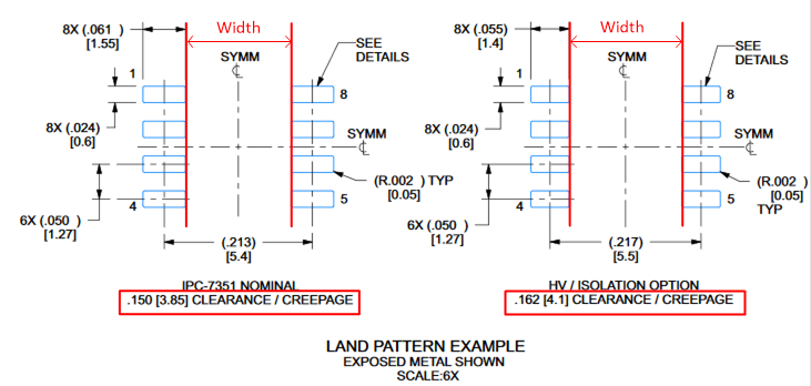
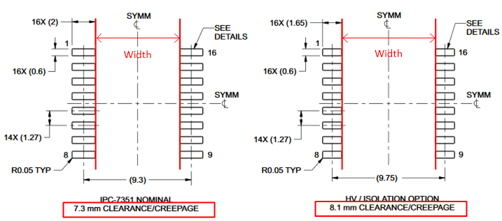
The isolation barrier width in the PCB can be set using the width between the isolated and non-isolated pads of the device. The minimum width varies with package, and for highest creepage and clearance use the widest land pattern possible. Reference land patterns are shown in pages 30 and 33 of the ISO7721 datasheet
For an ISO7721 in a D package, 3.85mm and 4.1mm widths of the isolation barrier are shown below:
and for an ISO7721 in a DW package, the width parameters are greater:
Is this the dimension you are looking for? Please let me know!
Thank you for your time,
Manuel Chavez
Hi Sirs,
Thanks for your reply.
We wonder if the CAN Bus can use the 100 ohm impedance control for cable instead of 120 ohm
since the 120 ohm impedance is not as common as 100 ohm impedance for cable vendors.
Hi Sirs,
Thanks for your reply.
Due to the ISO7721 have different reference GND,
Could you please help to confirm the minimum GND moat distance?
For example, due to we used the ISO7721FDR for the SOIC-8 D package,
The SOIC-8 widths is 3.85 mm, Does it meet the GND ISO moat need 3.85 mm?
Because the 3.85mm is too wide for layout design, Does it possible to reduce the width to meet design rule?
Hi Shu-Cheng,
Since the CAN standard is defined with 120 Ohm impedance cable, if 100 Ohm cable is used, it will not technically be CAN standard compliant. From a device functionality perspective, 100 Ohm cable can be used, and if you choose to use it, the termination resistor should match the cable impedance of 100 Ohm.
Regarding the ISO7721FDR, the isolation barrier or "moat" distance directly affects isolation rating. By reducing the thickness of the moat, please know that the creepage/clearance and therefore isolation voltage rating will decrease if there are exposed traces, pads, or device pins closer than the device's own creepage and clearance distance of 4mm
Thank you for your time,
Manuel Chavez