This thread has been locked.

If you have a related question, please click the "Ask a related question" button in the top right corner. The newly created question will be automatically linked to this question.

ISO1050: Low temperature start-up problem

Part Number: ISO1050

I have an ISO1050DUB application which is not powering up correctly at low temperatures.

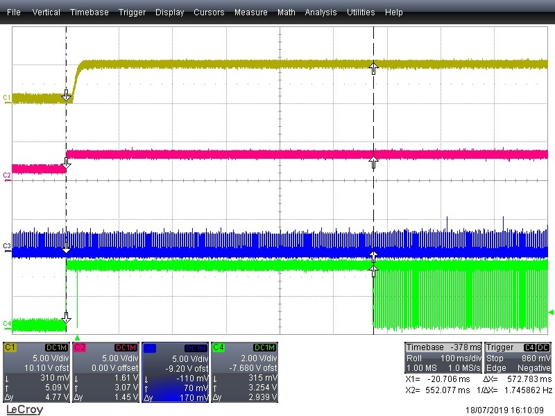
It appears only during recovery from brown-out conditions (removal of power for around 4 seconds) when tested at -33°C. There is a long delay in RXD data becoming available (up to 9 seconds) which is causing CAN errors.

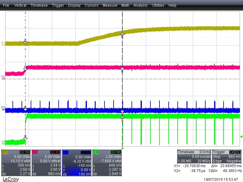
I have included scope traces below with the following set-up:

Ch1: VCC2 Isolated 5V (ISO1050 pin 8 w.r.t. pin 5)

CH2: VCC1 3V3 (ISO1050 pin 1 w.r.t. pin 4)

Ch3: CAN bus differential signal (CANH-CANL)

Ch4: RXD (ISO1050 pin 2 w.r.t. pin 4)

Power-on at 20°C:

RXD available after both supply rails have stabilized, as expected.


Power cycled off for approx. 4s at -33°C:

Delay in RXD becoming available. This can be up to 9 seconds after power is established which is unacceptable..

I need to know the following:

1. Is this a known behavior?

2. This appears to occur only during brown-out. If so, how long does power have to be removed to guarantee start-up? The application needs to operate down to -46°C.

3. Is there a solution available bearing in mind this is a common circuit used in a number of products so any non-pin compatible part change is unacceptable.


Thanks


  • Andy,

    Yes this is a known issue. This has been discussed by Dan Kisling (ISO CAN expert) in other threads. See this thread to learn how to address this issue. The section below from the linked thread is probably the most relevant to you..

    If the ISO1050 must be used, it is important to ensure that the power supply will discharge to 0V so that a longer than normal re-initialization time does not exist. If the power supplies cannot be configured in such a way that they discharge below 0.3V on their own, one can implement a bleed resistor between Vcc and GND. The bleed resistor value should be selected such that it ensures Vcc goes below the brownout window fast enough for any power interruption or power down sequence the system may permit. The lower the resistance, the faster Vcc will discharge to 0V at the cost of burning power. For many systems, a bleed resistor value of 2KΩ will work.

    Respectfully,

    Lucas

  • Hi Andy, 

    Just to add to Lucas's points here: there is not a pin-to-pin compatible part from TI to replace this device right now. The best solution I would provide for you is to see if you could add a bleed resistor. You may have the place in the layout if there was an extra decoupling capacitor footprint. 

    Which package variant of the device are you using? The 16-pin DW package or the 8-pin DUB?

    Please let us know if you have any additional questions. 

    Best regards, 

    Dan

  • Hi Dan,

    We are using the 8-pin DUB.

    The 2k bleed resistor resolved the issue. Interestingly, whilst there was bus activity VCC2 was held at 0.6V even when all power was off - the bleed resistor clamped this <15 mV.

    Thanks for your help.

    Best regards,

    Andy