This thread has been locked.

If you have a related question, please click the "Ask a related question" button in the top right corner. The newly created question will be automatically linked to this question.

ISOW7821: Can NC pins be connected?

Part Number: ISOW7821
Other Parts Discussed in Thread: MAX3221

I have a design based on AD's ADuM6201 that is faling EMC test; fixing it may be complicated. While looking for alternatives, I found ISOW7821 that could be a perfect drop-in replacement as far as package, logic I/Os and supplies are concerned (same package size, similar pinout). However, some pins that are NC on ISOW7821, have some function on ADuM6201 and are connected to either VCC or GND. I would like to know if these NCs could be connected to some logic level or they need to be left NC.

Other than that do you see any reason why it should not work as a replacement? FWIW it is connected to a MAX3221 on the secondary side and it isolates this port from a floating circuit of an applied part.

Thanks in advance.

  • Hi Elder,

    Thank you for considering ISOW7821 as a replacement in this opportunity. Yes, it seems to be a suitable replacement for ADuM6201, especially since the NC (no connect) pins are not connected internally to the device.

    Please allow our isolation team to follow up and confirm this response during business hours Monday - Friday.

    Thank you for your time,

    Manuel Chavez

  • Hi Elder,

    Like Manuel mentioned, the NC pins of ISOW7821 are internally not connected to the die. Hence, there shouldn't be any issues when you connect these pins to either VCC or GND.

    Could you please share details about the emissions issue that you are facing currently? Could you please share your current results for us to understand how far are you to meet your emissions requirement. Please do share the below information to be able to guide you better on reducing emissions in your application.

    1. What is your input voltage, output voltage & max output load on VISO pin of ISOW7821?
    2. Is it possible to share your schematic showing any EMI components that you are already using like common-mode chokes or Y-caps.
    3. What emissions standard do you have to meet? Like CISPR 22 Class A?
    4. Could you please share your current emissions test results?

    Please do also go through the below E2E post for more information on reducing emissions further. Let me know if you have any questions, thank you.

    Regards,
    Koteshwar Rao

  • Hello Koteshwar.

    Answering to your questions:

    1- 3.3V in and out, a few mA load on VISO (MAX3221 loading it).

    2- I would not like to share schematics right now. Anyway it is a first prototype that will be reviewed soon. No common mode chokes or Y-caps were used (I will add them, along with some small fixes in the circuitry and PCB layout).

    3- Yes, CISPR 22 class A.

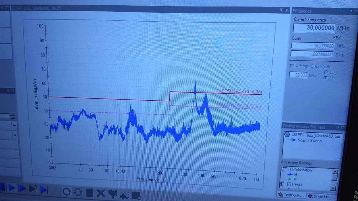
    4- See below a picture of the screen (peak sweep). What I find funny is that only the second harmonic of the isolator's power converter appears. 

    I will add the common mode choke and Y-cap as recommended in the App. Report. However, I think that only by the replacing ADuM6201 with ISOW7821, we would possibly meet the emission requirements (the  peak is at 350MHz). That is the reason why I asked this question, as ISOW7821 is practically a drop-in replacement, I may perform a quick preview right away.

    BR

    Elder.

  • I have an additional question regarding ESD protection.

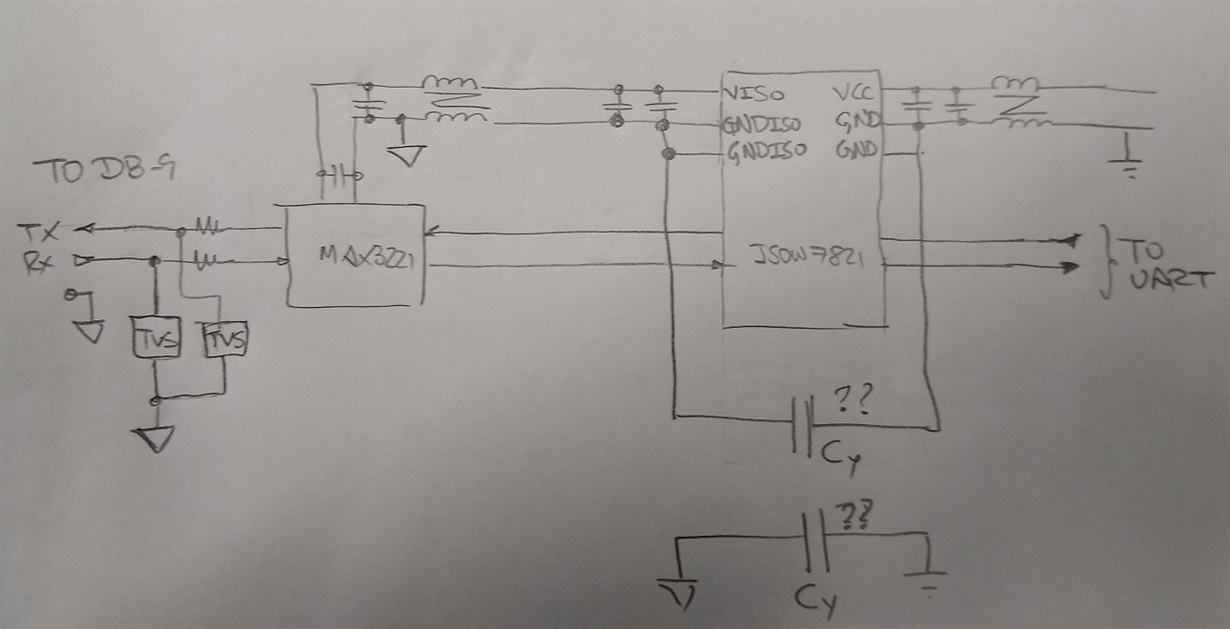
    If I add the common mode chokes as a EM emission reduction measure and a Y capacitor, where should the Y-cap go, on the ISOW7821 side or on the opposite side of them? To clarify, see diagram below.

    Any additional suggestion about protecting the circuit? It is subject to ESD only, no EFT or surges. On the other hand, I have been told that the lab applies 6kV contact and 15kV through the air discharges.

  • Hi Elder,

    That's a good question, thanks for sharing the diagram clarifying your question.

    ISOW7821 supports >8kV of ESD contact (Level 4) and hence it doesn't require any Y-Cap for ESD protection. However, it will be difficult to predict how much of 15kV ESD air discharge is going to appear across the device. Hence, to be prepared for the worst-case you can use Y-Cap for 15kV ESD air discharge protection.

    Please do note that 8mm clearance of ISOW7821 is not sufficient to meet 15kV of transient as air is going to break for any transients >13kV for 8mm clearance. Using Y-Cap might still help in meeting 15kV transient even though clearance is not sufficient. Please do share the part number of the Y-Cap that you are going to use.

    Regarding your question on Y-Cap connection, the cap should be connected to device pins directly to be effective. This means that Y-Cap should be connected to device GND and GNDISO pins directly and not the system GND planes.

    Please do share us both emissions and ESD results once you conduct these tests, thanks.

    Regards,
    Koteshwar Rao

  • Hello, Koteshwar 

    Re. the capacitor, I am considering Murata's DK1B3EA471K86RBH01 (470pF Y1 as I use it in some other positions and they are OK for BF type circuits as far as leakage current is concerned).

    About 15kV through the air, I am just guessing here as I am not that knowledgeable in this area (i.e. ESD protection) but I suppose the Y1 capacitor will, to some extent, act as a filter and reduce the peak voltage across the barrier (maybe a low capacitance stitched capacitor would be even better, assuming lower parasitic inductance may be achieved).

    About the Y capacitor positioning, one concern I have (and again, my limited knowledge in the area can make me miss important things) is the inductance of choke could make the TVS not as effective for MAX3221. That is why I considered the second Y capacitor in the diagram. Maybe I should use two caps of lower value instead of only one?

    Regards

    Elder

  • Hi Elder,

    Thanks for sharing the Y-Cap part number, I couldn't find its impedance vs frequency curve in the datasheet. This would have been useful.

    You are right about Y-Cap improving IEC ESD performance and we have seen this help sometimes. What I want to highlight here is that the capacitor is going to be effective if the clearance of the Y-Cap (also device in this case) meets the clearance requirement for the ESD.

    For example, to meet 8kV ESD contact a package with 8mm clearance is going to work fine if the device supports 8kV ESD. If the same device is packaged into a smaller package, let's say one with 4mm clearance, then this 4mm clearance package might not pass 8kV ESD contact test even though the die inside it is capable. This is due to the reason that 4mm clearance isn't sufficient for 8kV ESD and air with a dielectric strength of ~1.5kV/mm will break down and create sparks. This disturbance created in air could lead to indirect device damage. In this situation, adding Y-Cap may or may not improve. To support 8kV ESD contact, >5.3mm clearance is necessary for the air to not break.

    Similarly, a 4mm clearance package is going to support 6kV ESD contact. If the device is not capable to support 6kV ESD contact but the package clearance is 4mm then you can use a Y-Cap with >4mm clearance to meet 6kV ESD contact. This is where the Y-Cap is going to be effective where it improve overall solution ESD performance when clearance is met.

    Now coming to your application, I am not sure what is 15kV ESD air discharge equivalent to in contact discharge testing. I don't think it is easy to determine this. For our discussion, let's assume the worst-case that 15kV ESD air discharge is equivalent to 15kV ESD contact. To support 15kV contact, the min clearance required is for the package is 10mm. If the device supports 15kV contact discharge & package supports >10mm clearance then the device will pass 15kV ESD contact. If device doesn't support 15kV contact but package supports >10mm clearance then a Y-Cap with >10mm clearance can improve ESD performance and help the solution meet 15kV contact.
    Since ISOW7821 only supports 8mm clearance, it won't support 15kV contact but I am not sure how does it behave for 15kV air at application level. You could definitely try using the Y-Cap and see if this helps you meet 15kV air.

    The common-mode chokes (CMC) are on power supply lines while TVS is used on RS-232 bus. I do not think TVS diodes performance on RS-232 bus is impacted by the usage of CMCs on power supply lines. This shouldn't be an issue.

    Using Y-Caps on system GND planes could make the CMCs ineffective for radiated emissions reduction. Hence, I recommend to use Y-Cap on ISOW7821 GND pins directly.

    Sorry for the lengthy response, I hope this post doesn't create any confusion. Thanks.

    Regards,
    Koteshwar Rao

  • Hello, Koteshwar

    Thank you for the detailed explanation. I have no idea of what 15kV through the air is equivalent to.

    8kV contact is in the same line of the table as 15kV TDA  but I suppose they are not entirely equivalent.

    Anyway your post gives me a lot to think about.

    Regarding the capacitors, you may find more data in Murata's web page:

    https://psearch.en.murata.com/capacitor/product/DK1B3EA101K86RBH01.html

    https://psearch.en.murata.com/capacitor/product/DK1B3EA471K86RBH01.html

    BR

    Elder

  • Hello Elder,

    Thanks for sharing the links to the plots I was looking for. The data looks good, the 470pF cap could be useful for radiated emission as well. Thanks.

    Regards,
    Koteshwar Rao

  • Hello Koteshwar,

    Thank you very much for your support.

    Best Regards

    Elder