This thread has been locked.

If you have a related question, please click the "Ask a related question" button in the top right corner. The newly created question will be automatically linked to this question.

ISOW7840: Shielding with chassis ground traces along isolation barrier

Part Number: ISOW7840

Hi,
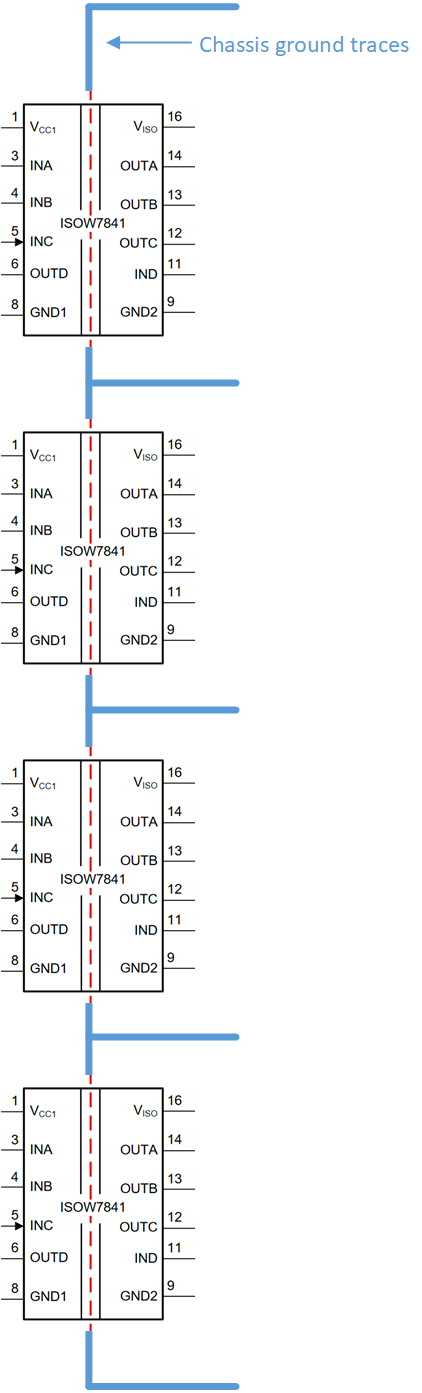
I am using ISOW7840 digital isolators in a design I'm currently working on to isolate four serial streams (9600 bps) from each other, with the output conditioners for each stream fed from the isolated supply of the respective isolator. Each of these interfaces is to be shielded by compartments in the metal enclosure of the device to reduce capacitive/inductive coupling between them. Due to space constraints on the PCB, I am considering placing chassis ground traces along the centre of the isolators (along the isolation barrier) as shown in the picture below (the traces won't run under the isolator chip). Could you please advise whether this approach would affect the performance of the ISOW7840 isolators? Do you have any advise on how the shielding of the isolated interfaces should be implemented?

Thank you,

David

  • Hi David,

    Thank you for posting to E2E and including a diagram of the desired setup. Routing chassis ground traces in between isolated and non-isolated sections of a PCB may not affect the ISOW7840's performance directly, but it will compromise the isolation barrier. Creepage and clearance specs of the ISOW7840 (>8mm) should be consistently maintained throughout the board's entire isolation barrier to maximize the isolator's performance, therefore, these traces are not recommended.

    Metal enclosures can be connected to a third (Earth) ground or one of the grounds on the PCB, so long as the creepage/clearance constraints are met all around the enclosure and there are no electrical connections across the isolation barrier.

    Reducing emissions from each stream can also be accomplished by using interlayer PCB capacitors or y-capacitors with each of the four streams. Is this something you could be interested in as well?


    Thank you for your time,
    Manuel Chavez

  • Hi Manuel,

    Thank you for your advice. I will avoid placing these traces across the isolation barrier.
    Yes, I am considering additional emission-reduction measures; however, I am considering CM chokes rather than the interlayer PCB capacitor.

    Best regards,

    David

  • Hi David,

    You're welcome! Common mode chokes can be helpful to include on the power supplies: are there certain frequency ranges you'd like to reduce emissions for?

    Since the ISOW78xx Isolated DC/DC converter switches at ~60MHz, the part numbers mentioned in the E2E post below may be good common mode chokes to consider.


    Thanks again for posting, and welcome to E2E!


    Have a great weekend,
    Manuel Chavez