This thread has been locked.

If you have a related question, please click the "Ask a related question" button in the top right corner. The newly created question will be automatically linked to this question.

ISO7740: ISO7740 interpretation of skew times

Part Number: ISO7740

Dear team,
I'm not 100% certain of how the different skew times play together regarding the overall skew.

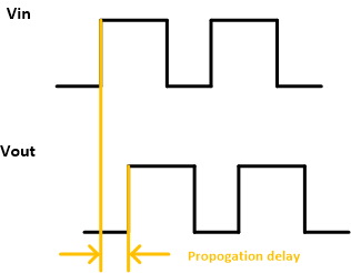
One of the times is t_sk(pp), the part-to-part skew time which is 4.4ns for the given device. I read the data so that when multiple inputs switch in the same direction (either HL or LH) the difference in propagation delay will be 4.4ns at max. between the slowest and the fastest propagation time.

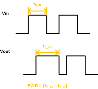
The other time is PWD, the pulse width distortion, which is 5ns for this device and describes the difference in propagation times between a HL and a LH change of the input.

For me that would mean that the worst case difference in propagation times can add up to 9.4ns if the part to part skew is at its limit and if two signals switch in different directions (one signal HL, another LH) and the PWD is also at its maximum value.

Is my assumption correct or do I miss something?

With best regards,
Torsten Lang

  • Hi Torsten,

    Welcome to TI E2E Forum and thank you for reaching out to us seeking clarifications.

    Please allow me to explain tsk(o), tsk(pp) and PWD before I get to the conclusion.

    Parameter tsk(o) [channel-to-channel output skew time] defines the maximum difference between propagation delays of any same direction channels of a given device. Since ISO7740 has channels only in one direction, tsk(o) for this device is going to be defining the maximum difference between any channel propagation delay times.

    Parameter tsk(pp) [part-to-part skew time] defines the maximum difference between propagation delays of any same direction channels of different devices. Since ISO7740 has channels only in one direction, tsk(pp) for this device is going to be defining the maximum difference between any channel propagation delay of one device to any channel propagation delay of another device. Please note that the earlier parameter tsk(o) compares different channels in one device while tsk(pp) compares channels between different devices. This is the only difference between these two parameters.

    PWD defines the difference between HIGH-to-LOW and LOW-to-HIGH propagation delays of a given channel for a given device. Unlike the above two parameters, PWD is comparing two propagation delay times of a single channel.

    The above parameters describe that there is going to be differences in propagation delay times between two different inputs of a channel, between two channels of a device and between two channels of two different devices. Even though these differences exist between channels and devices, the propagation delay of each individual channel for any given device will still be under the specification defined as propagation delay time (tPLH, tPHL) in datasheet. This means that tPLH and tPHL specs already cover PWD, tsk(o) and tsk(pp) variations.

    I hope this clarifies your confusion, let me know if you still have any questions. Thank you.

    Regards,
    Koteshwar Rao

  • Hi Koteshwar,
    unfortunately this does not help with my problem. I have a timing requirement that the arrival times of the signals of a parallel bus at the output must not by any means differ more than approximately 5.5ns (I may be able to push this to 6.25ns, but not more). The propagation delay itself unimportant to me as the bus is unidirectional (clock, a start of frame and the data bits).

    So, first of all, tsk(pp) (the bus requires 5 ISO7740) must not be greater than this value.

    BUT: tsk(pp) is for all signals switching in the same direction. This is where PWD comes into account. So the question is: Does PWD just cover tsk(pp) (which would be OK for my application) or does it add up to tsk(pp) (which would make the ISO7740 unusable for my application).

    With best regards,
    Torsten

  • Hi Torsten,

    Thank you for posting to E2E! Your understanding of part-to-park skew, t_sk(pp), is correct. This parameter quantifies the range in propagation delays across multiple devices under identical conditions.

    As Koteshwar said, Pulse Width Distortion, is different than propagation delays. Instead of describing a shift in time, this is a measurement of the possible difference in duration of a pulse between its input to an isolator and output, already considering propagation delay times. Simplified definitions of the two terms are given in the diagrams below:


    Thank you for your time,
    Manuel Chavez

  • Thanks Manny,
    for additional inputs.

    Hi Torsten,

    Thanks for clarification and sharing additional inputs on why this is important for you. I see now why the overall part-to-part skew time is important to you considering both HL and LH inputs. I understand your question that you wanted to know if the overall part-to-part skew time will be the sum of tsk(pp) and PWD. The answer is yes, this is going to be an addition but it wouldn't be a direct addition.

    I would have to work with other members in the team to see if we will be able to provide the worst-case overall tsk(pp) considering both HL and LH inputs. Please allow me to come back to you on Monday on this, thanks.

    Regards,
    Koteshwar Rao

  • Hi Manuel,
    yes, that's my understanding of both effects. But the interesting question is how these interact. What Koteshwar summarizes in is last post is exactly the overall effect that is relevant for my application.

    Hi Koteshwar,
    did you and the team come to any results yet?

    Regards,
    Torsten Lang

  • Hi Torsten,

    Thanks for waiting.

    I was able to find out the worst-case part-to-part skew considering both LH and HL inputs. Please find below the data along with the assumed test conditions.

    Test Conditions:
    1. VCC1 = VCC2 = 5V±10%
    2. TA = -55C to 125C
    3. Input = LH, HL
    4. Load = 15pF

    Part-to-part skew considering both LH and HL inputs:
    Max tsk(pp)(LH,HL) = 6.4ns

    Please do note that the above skew data is max skew considering temperature variation. I believe all 5 ISO7740 devices in your application will be experiencing similar temperatures and will not have extremely opposite temperatures. When the temperature variation is eliminated, the skew value is expected to be much lower than 6.4ns. Unfortunately, I do not have a split of skew data for individual temperatures instead only have data for overall temperature range.

    Considering that skew is going to be much lower than 6.4ns for given temperature, I hope you will be able to consider using ISO7740 in your application. Let me know if you have any other questions, thanks.

    Regards,
    Koteshwar Rao

  • Hi Koteshwar,
    thanks a lot for your investigation. As we operate the hardware at 3.3V, the single times PWD and tsk(pp) are about 0.1ns higher, so am I right to assume that the overall tsk(pp)(LH,HL) will be around 6.5..6.6ns then?

    Regards,
    Torsten Lang

  • Hi Torsten,

    I apologize for not notifying you sooner: Koteshwar is currently out of the office. Please expect his response early next week.


    Thank you,
    Manuel Chavez

  • Thanks Manny.

    Hi Torsten,

    Apologies for the delay due to travel.
    Though your assumption of considering tsk(pp)(LH,HL) to be about 0.1ns or 0.2ns higher at 3.3V is fair, we would to have combine the LH and HL skew at the source to get accurate and realistic worst-case skew data. Since the timing specs are expected to be similar between 5V and 3.3V, we don't have this data available for 3.3V separately and hence, I cannot confirm the exact value of overall skew for 3.3V.

    If this data is critical for you, then we can run the necessary tests at 3.3V to get you the realistic overall skew. When we run the tests, we will be able to run the tests for various temperatures separately and provide worst-case skew for any given temperature (as against the data I provided earlier considering temperature variation as well).

    Please do confirm, once you confirm I will need 2/3 days to get this data. Thanks.

    Regards,
    Koteshwar Rao

  • Hi Koteshwar,
    I suppose currently there is no need for further action. The worst case overall skew times are a bit too high even at 5V, so we discussed to limit the data rate by either reducing the number of channels or by reducing the sample rate of the device.

    I will come back when further questions arise.

    Regards,
    Torsten

  • Hi Torsten,

    Thanks for your inputs. Please do note that the 6.4ns skew data that I had provided for 5V is considering temperature variation while the tsk(pp) spec given in datasheet is applicable for a fixed temperature. This means that tsk(pp) is the max skew between two parts where both parts are powered with same VCC voltage, operated at same temperature, same input and same load.

    Considering the same conditions, tsk(pp)(LH,HL) for any given temperature is going to be about ~5ns. Please note that this is still more than worst-case data as the LH and HL data here is combined at later stages. The more accurate skew is obtained when we combine LH and HL data at source and this is expected to be lower than 5ns. This means that the device meets your requirement.

    Please do feel free to let us know if you still have any questions or concerns. Thanks.

    Regards,
    Koteshwar Rao