This thread has been locked.

If you have a related question, please click the "Ask a related question" button in the top right corner. The newly created question will be automatically linked to this question.

ISO1541: Isolation of EVM2300

Part Number: ISO1541
Other Parts Discussed in Thread: BQ34Z100-G1, , BQ34Z100, ISO1540, TCA9517A, TCA9800

Hi

I am trying to isolate EVM2300 from custom board developed based on BQ34Z100-G1. I want to log charging and discharging as isolated. 

I have used ISO1541. Side1 is connected to EVM2300 and Side2 is BQ34Z100. VCC is 3V3 for both sides. Pull-ups are 1.5k and also 0.1uF decoupling capacitors used.

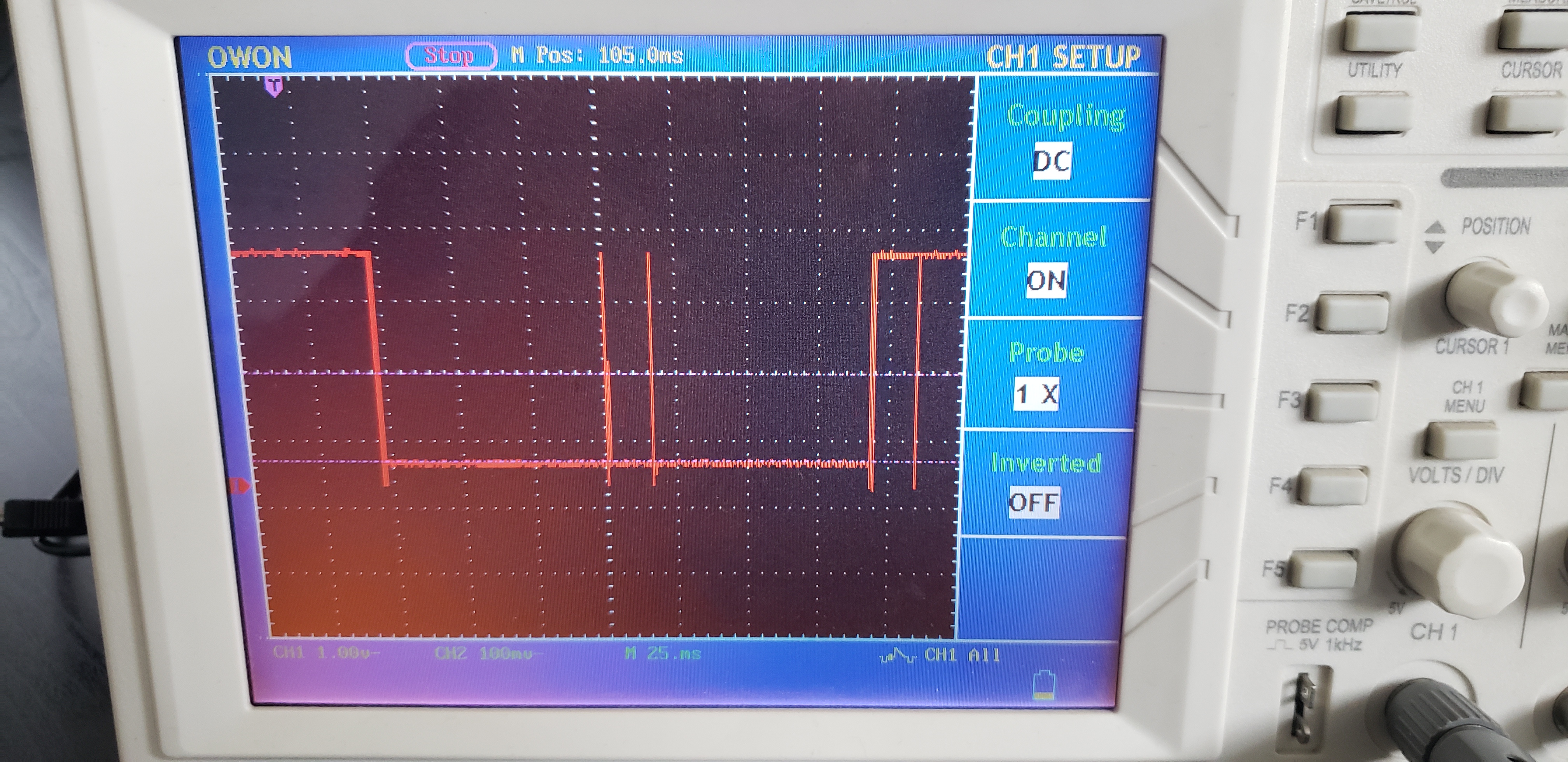
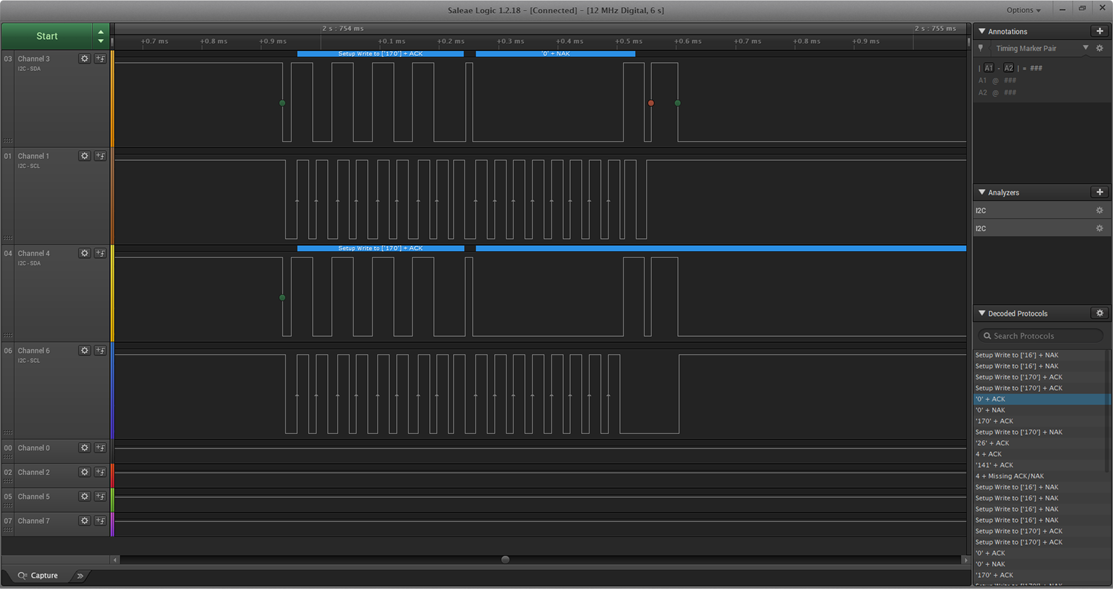
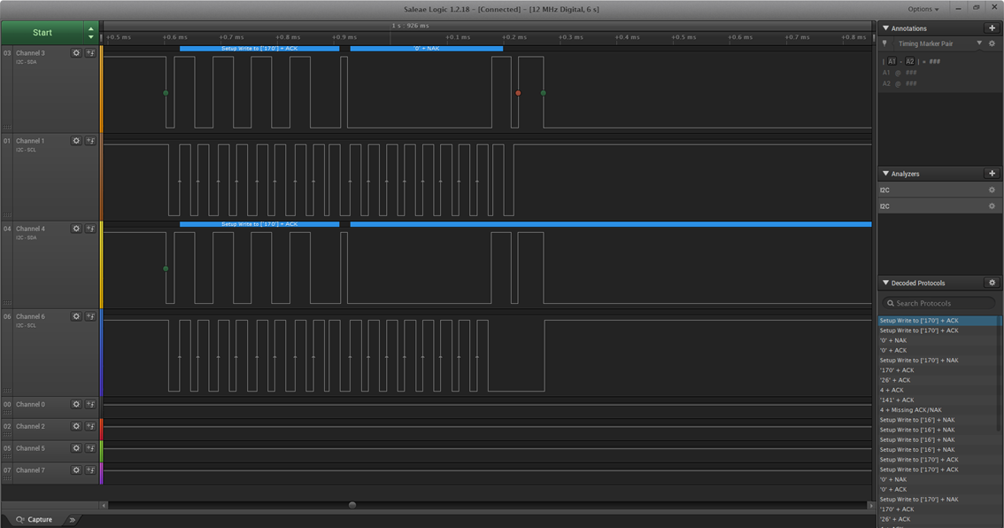
But I could not get any response from chip. I could get if I driectly connect EVM2300 to chip.

I am not sure ISO1541 is correct selection or should I change that with ISO1540?

Thanks

  • Hi Mehmet,

    Thanks for posting on E2E!

    Looking over the two EVM's schematics, I believe ISO1541 fits well for this application. ISO1541 has a uni-directional clock line which simplifies the solution for single-master systems without clock-stretching slaves. This should not impede normal data-flow like you describe. ISO1540 may be easier to implement because either side may be used for the I2C master, allowing the side choice to be done based on input threshold requirements. 

    Concerning the communication issue, most I2C isolators such as ISO1541 require pull-up resistors to be included on both sides of the device. It appears that neither EVM schematic includes these resistors so they would have to be added externally. Could you confirm that pull-up resistors are included on both sides of ISO1541?

    If this is not the issue, would you be able to share a bit more information about your system and the testing you're conducting? A schematic of the way the two boards are connected (including supply and ground connections) would be useful as well as scope shots from both sides of the device while communication is being attempted. I'm particularly interested to see the output of side 1 when side 2 is driven and vice versa. 

    Please keep us updated on your progress with your design using ISO1541 and let us know if you have any more questions.

    Regards,
    Eric

    [Edit]: corrected device name typos

  • I have attached schematic of circuit.

    Also logic analyzer results as follows. There is some missing portions on communication but I don't know how to correct that. I have tried so many pullup resistors and could not succeed reliable communication.

    Setup Write to [4] + NAK
    Setup Write to [4] + NAK
    Setup Write to ['16'] + NAK
    Setup Write to ['16'] + NAK
    Setup Write to ['170'] + ACK
    '0' + ACK
    '170' + ACK
    4 + ACK
    4 + Missing ACK/NAK
    Setup Write to ['16'] + NAK
    Setup Write to ['16'] + NAK
    Setup Write to ['170'] + ACK
    '0' + ACK
    '170' + ACK
    4 + ACK
    4 + Missing ACK/NAK
    Setup Write to ['16'] + NAK
    Setup Write to ['16'] + NAK
    Setup Write to ['170'] + ACK
    '0' + ACK
    '170' + ACK
    '170' + ACK
    '170' + Missing ACK/NAK
    Setup Write to ['170'] + ACK
    '0' + ACK
    '170' + ACK
    '170' + ACK
    '170' + Missing ACK/NAK
    Setup Write to ['170'] + ACK

  • Hi Mehmet,

    Upon further review, it looks like the the thresholds and output characteristics for ISO1541 and BQ8015DBT (I2C device on EV2300) have tight tolerances with each other. This may explain why some of the communications succeed while others appear to fail or are unrecognized. I first recommendation would be to use larger valued pull-up resistors on this side to try and decrease the low-level voltage. It sounds like you have already tried a few values, but I'd like to confirm that failure still occurs when a pull-up on the order of 5k-ohm or so is used. Would you share what values were used? I would also be interested to see analog scope shots of the I2C lines during the communication to see if the thresholds are indeed causing the issue. 

    If this does not resolve the issue, I would recommend the use of a different non-isolated I2C buffer such as TCA9800 or TCA9517A. Both of these options have higher threshold values and lower output voltages than ISO1541. I suggest non-isolated interface parts because I understand the current application for ISO1541 is for development and test. If isolation will be a requirement for later interrations, let me know. Let me know if you have questions about these devices or would like other recommendations.

    Please let us know what results of your tests and if you have any more questions.
    Regards,
    Eric

  • Hi Mehmet,

    I'd like to comment on my previous reply. An I2C buffer such as TCA9800 or TCA9517A could be used in series with ISO1541. These devices can translate the signal to/from ISO1541 to appropriate voltage levels for BQ8015DBT. This would also require pull-up resistors to be added between the selected buffer and ISO1541. This configuration would still provide the isolation barrier of ISO1541. 

    I would also like to point out that on the schematic that you shared, the SDA1 pin of ISO1541 does not appear to connect to the EV2300 header. It seems this is a mistake with the schematic as you show that there has been some successful communication, but I wanted to mention it nonetheless. 

    Also, I would like to correct my typo in the previous reply. I suggest the use of a pull-up on the order of 5k-ohm, not 5-ohm. I have fixed this with an edit for clarification.

    Regards,
    Eric

  • Hi Mehmet,

    I wanted to follow up on this thread. Have you been able to make progress with your design isolation EV2300? If you were able to find a solution, we would be interested to hear what it was. 

    Regards,
    Eric

  • Hi Eric

    I am suspicious about faulty chip. When I check Side B signal with 4.7k pull-up resistor, there are meaningless outputs observed. So I have ordered new one to try again.

    Will let you know in a few days. Thanks for your concern.

  • Hi 

    I have tried with new chip. 

    Side1 with 5.1k, Side2 with 2.2k

    Still could not communicate through isolation. Oscilloscope image is attached on Side2 SDA. Some glitches are being seemed.

  • I have tried so many combinations but no luck. That should not be so hard to use such an isolator. I am suspicious about it is a well designed chip.

    I have connected Side1 to EV2300 and kept pull-up resistors 5.6k. Higher values did not work.

    Custom designed board connected to Side2 and so many pull-up resistors tried from 1k to 37k. Some of logic results attached.

    I have broken the isolation to check both side signals in sync. On below graphics first two rows are about Side1 and the others are about Side2.

    That seems there is always somehow one clock signal is getting missed.

    Communication is at 100kHz, I have also tried 400kHz but did not work neither.

    Side1: 5.6k  -  Side2: 1k

    Side1: 5.6k  -  Side2: 2.2k

    Side1: 5.6k  -  Side2: 22k


  • Hi Mehmet,

    In the logic analyser shots your shared, it appear that the slave device is attempting to stretch the last clock bit of this sequence. Looking further into the datasheet for BQ43Z100, it looks like this is indeed a function of the device's I2C driver. Because ISO1541 has a unidirectional SCL line (side 1 to side 2), it would be unable to communicate this stretch back to the master - thus the slave misses a clock cycle and communication fails. Because all other data looks to be properly propagated through the device, I believe this may be the cause of the issue. To resolve this issue, I would recommend using ISO1540 which has a bi-directional SCL port so that the data sent on the clock line by BQ43Z100 can be propagated to the system master.
    I realize that you inquired about this difference in you initial question and I apologize if I implied this would not be a potential solution. 

    Regarding the glitches apparent in the scope shots you shared, we would like to see scope shots from both sides of the device (on the same screen such as what is depicted in the logic analyzer shots). I'd like to see if the glitches are propagated through the isolator or if they only appear on one side. If possible, zooming in further to see the pulse-width and slew rate of the glitches would help identify a cause. 

    Knowing the minimum voltage on the scope shots on both sides will also indicate if the pull-up resistor selection is creating appropriate low-level voltages. Based on the behavior of the I2C devices given the logic analyzer shots, I believe the combination you are using will work. 

    I hope this helps and I look forward to hearing about the results. 
    Regards,
    Eric

  • Thank you Eric

    I am having trouble to get scope shots. I have ordered sample for ISO1540, when it is delivered I will give it a try then write the results again.

  • Hi Mehmet,

    I wanted to follow up on this thread. Have you been able to learn anything new regarding the glitches that appeared on the shared scope shot? Have you been able to test the solution using ISO1540?

    Regards,
    Eric

  • Hi Mehmet,

    This thread will be closed due to inactivity. Please feel free to post a follow-up question on this thread or by using the red and yellow buttons in the upper right corner of this window.


    Thank you,
    Manuel Chavez

  • Hi

    I am still waiting samples to be delivered. As soon as I get I will give it a try with ISO1540. I think problem is about bidirectional/unidirectional clock.

  • Hi Mehmet,

    I hope you have been able to make progress on your testing. Please let us know your findings when you are able to complete trials with ISO1540.

    We will close this thread soon due to inactivity, but you may re-open it by replying within 60 days of the previous reply or link to this thread with "Ask a related question". 

    Regards,
    Eric