This thread has been locked.

If you have a related question, please click the "Ask a related question" button in the top right corner. The newly created question will be automatically linked to this question.

ISO7821: Isolation forum

Part Number: ISO7821
Other Parts Discussed in Thread: ISO7841

We plan to use the ISO7821 DWW16 within a gate drive system for IGBT traction converters in railway application. The shape of the working voltage over the component is rectangular in a chopper function with resistive load (over voltage limiter). The rms voltage value is in this case depending on the modulation degree between the pulsewidth and on time, which can be between 0% up to 100% according Urms = UIOWM = U_dclink * square root (t1/t).

The application maximum voltages are 

Maximum repetitive peak isolation voltage VIORM (PK):  2770Vpk (ISO7821 data sheet max value = 2828Vpk)

Maximum working isolation voltage VIOWM (DC): 2300Vdc (ISO7821 data sheet max value = 2828Vdc)

Maximum working isolation voltage VIOWM (RMS): 2185Vrms (ISO7821 data sheet max value = 2000Vrms)

The application maximum values are below the datasheet values except the VIOWM (RMS). This value is exceeded by 185Vrms. This operation point of the converter is approx 1% of the total life time.

For my understanding, we are below the isolation and lifetime relevant values, the VIOWM (RMS) is some kind of "calculated equivalent" for the DC values .Maybe the time dependent brake down (TDDB) test has been carried out with a sinus shaped test voltage only. 

Question 1: Can we use the ISO7821 in our application even we exceed the VIOWM (RMS)? 

Question 2: Is it possible to conduct the TDDB test with a PWM shaped voltage to verify the lifetime? If yes what is the test specification?

Question 3: Is there an alternative component or maybe stacking of 2 in series (with defined centerpoint). Stacking is not a preferred solution.

This component is very intresting for traction converter in railway systems, as we have sinus- and rectangular shaped voltages, depending on the converter function.

Thank you for you valuable answer, and please come back with detailed questions

Klaus

  • Hi Klaus,

    Welcome to TI E2E Forum!

    Thank you for sharing the details related to your requirement for showing interest in ISO7821 in DWW package. ISO7821 in DWW package is a niche device best suited for applications requiring high working voltages and your application fits right in this category. Please see below my answers to the questions you have listed.

    A1: From your description, I understand that working 2185Vrms is exceeding the VIOWM spec of ISO7821DWW by 185Vrms. You also mentioned that the excess 185Vrms operation point only happens for 1% of your total product life time.

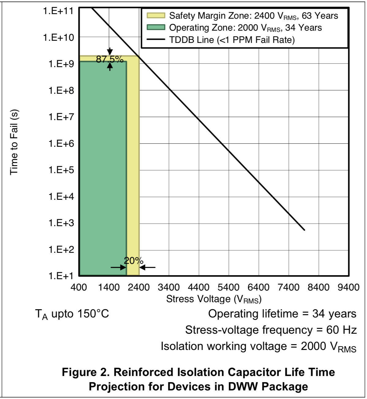
    I think 185Vrms over VIOWM rating is relatively a small value and the occurance of this excess voltage is also only for 1% duration. I believe this shouldn't be an issue for ISO7821DWW and there shouldn't be any noticeable degradation in the device lifetime. Please refer to the TDDB data of ISO78xx shown below (also found in ISO7841 datasheet). The device supports 2400Vrms with 63 years lifetime, with VDE safety margins the device is rated at 2000Vrms with 34 years lifetime by VDE. When I average out 1% of 2185Vrms with 99% of 2000Vrms, I get 2001.85Vrms and the lifetime at this voltage is ~33.9 years with safety margins as considered in the below plot. Hence, I believe this shouldn't be an issue.

    A2: The TDDB test at TI is conducted with AC voltage with 50/60 Hz frequency and the all the DC parameters are derived from the AC testing. I believe a the performance with a rectangular or a sinusoidal AC waveform should remain the same. These devices are already largely used in traction inverters which have rectangular HV appearing across it.

    A3: From the above analysis, ISO7821DWW should already suffice your requirement and you may not need an alternate solution. When needed, 2 devices in series can be used to achieve higher working voltages but this needs to be sufficiently evaluated to understand the voltage distribution across devices.

    I hope the shared information helps you make a decision on choosing the device. Let me know if you have any other questions, thank you.

    Regards,
    Koteshwar Rao

  • Dear Koteshwar

    Sorry for my late response to your very valuable and detailed information. You have exactly met the subject. I have investigated and verified a bit more details regarding the real mission profile in our application together with my colleagues and come back with 3 questions, which should then be complete for the go for ISO7821.

    1: What is the lifespan of the ISO7821 if it is continuously loaded with 2185Vrms?

    2: Does a higher stress voltage frequency of e.g. 1000 Hz or 4000Hz affect the lifetime?

    3: I see that you have experience with series connection of ISO7821. Do you have application hints?

    The best regards from Switzerland, Klaus

  • Hi Klaus,

    Thanks for reaching out and sharing inputs regarding your updated requirements. Please see below my inputs to the questions you have listed out.

    1. As per the raw test data, the lifetime of ISO7821DWW at 2400Vrms is 63 years while at 2185Vrms is 169 years. When VDE margins are considered (i.e., 20% margin on high voltage rating while 87.5% margin on lifetime), lifetime at 2000Vrms is 34 years while at 2185Vrms it is 15 years.
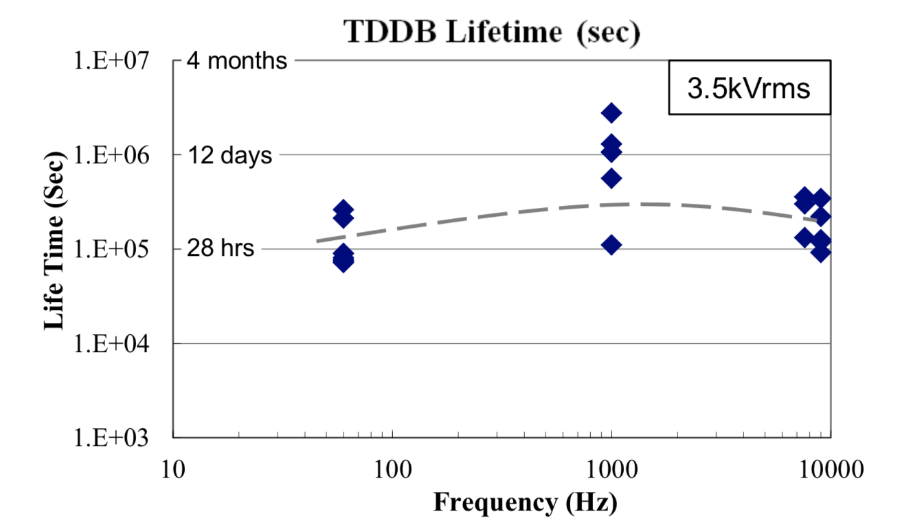
    2. Since our isolators are commonly used in motor drive and solar inverter applications that switching at a few kHz frequency, we did run a few some tests to determine the impact of HV switching frequency on device lifetime. Our study indicates that there is no noticeable impact on device lifetime due to higher switching frequency. Please note that we could only run these tests upto 10kHz due to switching frequency limitation of HV equipment. Please see the test results below.
      1. Please also note that, the tests were run at higher voltages (3.5kV) to keep the lifetime to a lower value (28 hours) so that the test is completed in a reasonable time for given test frequency.
    3. We do get requests from customers seeking for isolation devices with working voltage >>2kVrms. In such situations, we request customer to use more than one device in series to increase overall working voltage.
      1. Please note that working voltage distribution across the isolators in series is mostly proportional to their respective isolation capacitance (stated as CIO in datasheet).
      2. To avoid variation in HV split across devices, one can use external Y-capacitors that are much higher in value than CIO of device to better control the HV distribution.
      3. It is also important to under the capacitance variation of external Y-caps used and sufficiently test for voltage distribution.

    I hope these points answer your questions, thank you.

    Regards,
    Koteshwar Rao

  • Dear Koteshwar 

    Thank you for the detailation. All my questions are answered.

    We will test now ISO7821 within the real application and take care about the symmetrical voltage across both isolators.

    Again thank you for the very helpful information with a highly proffessional background.

    Best regards, Klaus