This thread has been locked.

If you have a related question, please click the "Ask a related question" button in the top right corner. The newly created question will be automatically linked to this question.

TLK2711-SP: Is there an EYE diagram mask definition available?

Part Number: TLK2711-SP

Dear TI,

I would like to setup a mask test on my oscilloscope to verify the eye diagram of the TLK2711 chipsets on my board.

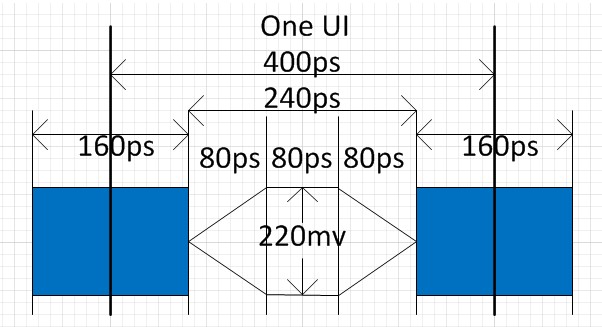
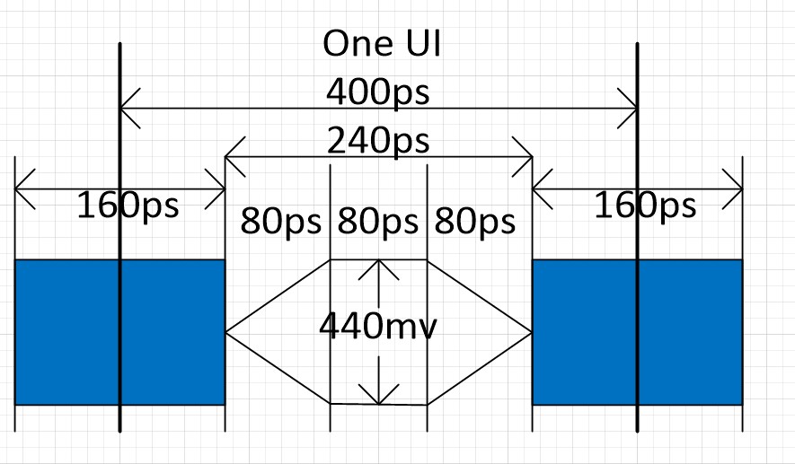
Is there a definition available of how the diamond shape mask should look like at e.g. minimum and maximum operating frequency?

I can try to define it myself by using the min/max voltage levels, rise/fall times and allowed jitter, but if that kind of information is already available I would really like to have it.

Many thanks and best regards,

Jeroen van der Velden


  • Jeroen,

    We have not performed any mask testing, so a mask has not been defined.

    However, several years ago I created a template for a mask based on the input requirements.

    The jitter tolerance eye closure is defined as 0.4UI.  At 2.5Gbps, this is 0.4*400ps = 160ps.  This is the amount of the eye that can be closed.
    Said differently, 0.6UI needs to be open at zero crossing. This is 240ps
    The rise and fall time in the datasheet are typical of 150ps at the transmitter.
    At the receiver, they will very likely be degraded significantly.
    A reasonable estimate would be to use the 160ps of closed eye to get full rise/fall for the 220mv min VID.
    This would leave 1/2 of this for the triangle portions of the diagram.
    Here is what I estimate would be a valid eye mask.

    If this answers your question, please click "Verify it as the answer"
    Regards,
    Wade

  • Hi Wade,

    Thank you very much for the template and explanation, it's really useful.

    Regards,
    Jeroen
  • It was noted that this eye was based on single ended, and not differential.

    The correct estimated mask for the full differential pk pk input for receiver would be 2x in height.