This thread has been locked.

If you have a related question, please click the "Ask a related question" button in the top right corner. The newly created question will be automatically linked to this question.

74ALVC244 - Overshoot

Other Parts Discussed in Thread: SN74ALVC244, SN74HCT244

Dear,

I'm using 74ALVC244Pw as output buffer for synchronisation signal 25Hz and 25kHz.

Line are used 2 by 2, delay between these 2 signal must be reduce, so I have chosen a fast logic.

74ALVC244PW is OK for speed, but there are overshoot on the output. Overshoot level is 70% : 5V for a 3.3 TTL logic. Ouput capacitor is 100pf for ESD.

How can I reduce overshoot with modifications as low as possible. I may increase output capacitor ?

Regards,

Aymeric

  • Aymeric,

    Can you post a schematic and scope shots of the overshoot?  Without seeing the circuit, I would recommend adding a small series resistance (5 to 10 ohms) to the output to reduce this overshoot.  Unfortunately, any R or C you add to the circuit will cut your bandwidth.


  • Thank you for your help.

    Schematic, is simple : FPGA => 74ALVC244 => 100pF => Connector

    Power supply is decoupled using 100nF 0603 X7R capacitor.

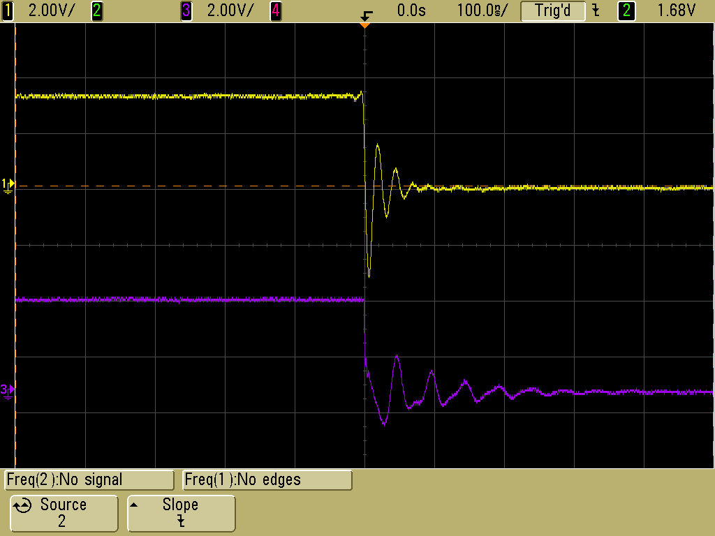
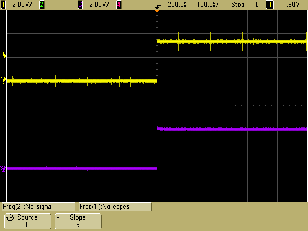
    Scope shot :

  • I made new measure testing RC filter.
    Signal are too differents : 25Hz and about 25kHz.
    Main problem is that RC delay depends of frequency, so if the same RC is placed on both signal, delay will not be the same.

    Our customer request that delay between the signal must be lower than 0.5ns.

    I may change
    74ALVC244 slew rate is 5ns/V.
    74LVC244 slew rate is not indicated in datasheet
    74ALVTH slew rate is 10ns/V
    Maybe changing buffer will solve problem.
  • Aymeric,

    It looks to me like there is approximately 3 V of overshoot on the input signal in the first scope shot.  That puts the input well outside the rated maximum (-0.5 V) and can cause problems.  I would recommend adding a clipper circuit on this input so that it cannot exceed the rated maximums.

  • Are you using the TI version of 74ALVC244 (ie SN74ALVC244)?

    Our SN74HCT244 has lower current drive but the same functionality that might also fix the problem.
  • Thank you.

    TI version is mounted on the board.
    74HCT is less speed, maybe to slow and may be tested.
    But it's a 5V power supply component.

    74LV244 may be a solution, 100ns/V is too low :
    considering rise time / fall time < 2% of period
    2 x 330ns < 2% of period => 30 kHz max

    50ns/V would be a good value bus several parts are not specified for this point (LVC244, LVT244...).


    Clipper circuit will solve half the problem but
    - it don't explain the source of the overshoot, -3V to +5V oscillation on LVTTL logic output
    - second overshoot may be see as a high level signal

    It may be PCB design, overshoot is present at the output of the component and it more important on the connector.
    It's probably HF impedance probleme, because using 20MHz scope Bandwith there's no problem. Probe ajustment change the signal.
  • Hi,

    New day, beginning of the solution :

    74LVC2244A :
    The outputs, which are designed to sink up to 12 mA, include equivalent 26-ohm resistors to reduce overshoot and undershoot.

    Output are described as LVTTL on this page :
    www.ti.com/.../SN74LVC2244A;tisearch=Search-EN-Everything
    but this caracteristic is not written on datasheet.

    Main avantage : resistor is placed on the input, on PCB, output resistor would be placed close to component but not enought.
    Maybe 100pF output is not necessary.
  • If the input waveform is the same to the 74LVC2244A it will still be violating the absolute max ratings of the part. A -3 V input signal is going to cause problems with pretty much any part I can think of -- that's why I suggested the clipper circuit for input signal conditioning.
  • Waveform are ouput of 74ALVC244.
    Over and under shoot are generated by ALVC244. What's why I need to change it.
  • So the scope shot is showing two outputs with no inputs? No wonder I was confused. You are only giving me tiny parts of the picture, and helping is very difficult when this happens!
  • Yes I written it on my firt post.
    Maybe I would have rewrite under the scope.
  • Aymeric,
    What kind of oscilloscope probe are you using to measure the output of this device? The frequency of ringing is very high, which makes me think that you might be using a probe with a long ground wire. Is that the case? Can you please test the device using a probe with a shorter ground wire and see if you are still getting that overshoot?
  • I'm using a 300MHz bandwith oscilloscope with it's standard probe.

  • Good news.

    Probes are quites bad, GND wire has more than 0.3 ohms serie resistor

    But changing component is a good way,

     - no more undershoot and less overshoot

     - 100 pF seems to high, but no capacitor is not good, overshoot increase comparing to 100 pF

     Datasheet indicate that measure are made with 50pF / 500 ohms load. I'm going to test these values.

  • Finally, solution is use 74LVC2244A,

     - undershoot < 0.5V

     - overshoot < 0.3 V

    Residual problems may be due to probe. But I don't have better probe to test.

    A 9th signal is drived by 74LVC1T45G. Solution to limit over and under shoot is increase output capacitor. No timing problem on this signal, at 25HZ, rise time up to 50 ns @ 5V is OK (10ns / V).

    Thank you for your help.