This thread has been locked.

If you have a related question, please click the "Ask a related question" button in the top right corner. The newly created question will be automatically linked to this question.

CD4033 frequency counter circuit question about power up problem

Other Parts Discussed in Thread: SE555, TINA-TI

Hi,

Firstly, my apologies, I'm a novice with a pretty mundane and 1970's style question about analog ICs for a very simple circuit.

I'm trying to make a simple analog frequency counter using the CD4033BE.  I have made a pulse timer with the CD4026 and that circuit powers up and functions fine so far.  The CD4033  frequency counter powers up terribly: some of the six LED 7-segment digits appear to be all segments on, the counter doesn't count for about thirty seconds, and then it slowly starts counting correctly but in an incremental manner until it reaches the accurate reading and then it finally continues correct Hz counting, e.g.

Power up: 0 0 8 1 8 8

30 seconds on time: 0 0 8 1 4 2

45 seconds on time: 0 0 8 0 5 8

50 seconds on time: 0 0 2 3 5 8

51 seconds on time: 0 1 4 3 5 6

(etc.)

55 seconds on time: 0 7 4 3 2 1

(etc.)

60 seconds on time: 1 6 4 7 1 7

61 etc. seconds on time: 1 6 4 7 1 7

I have only been learning about circuits for about 8 months or so, so (I lack practical experience in circuit design) am perplexed as it looks like some stupid simple problem I haven't come across before and trying a power up reset with a capacitor and a resistor on the 4033s hasn't helped (but which has always worked with the CD4017), the sequence is the same: the fourth 4033 (which counts thousands) is a stubborn "8", and the whole circuit suffers from what looks like a glitch similar to a stuck record loop, and when it finally escapes the loop it is slow to function correctly.

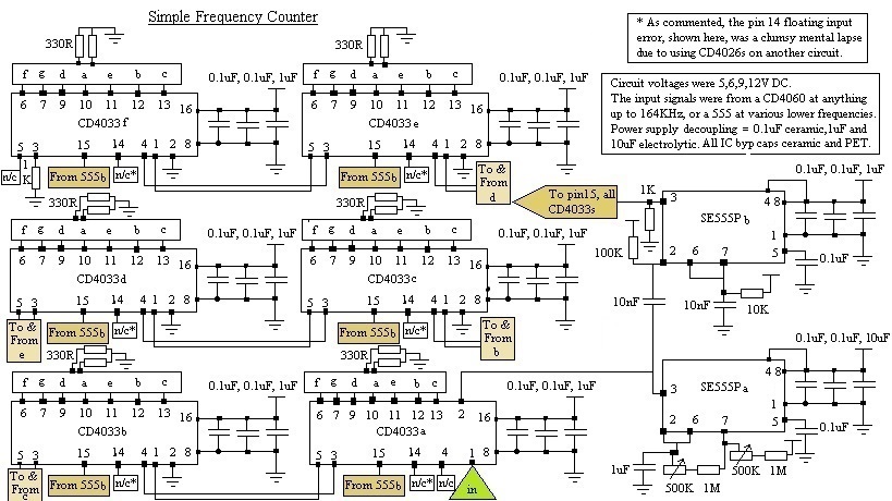
I have a multimeter with a frequency counter, so I know that my simple counter functions correctly once it has warmed up.  The circuit is 6 4033s, with the ripple blanking function enabled, and they count for 1 second and then are clock inhibited for 1 second to hold the count by a SE555, and then they are reset by a second SE555 with a "microsecond" pulse to the reset pins.  Whether the circuit runs off 5, 9 or 12 volts it exhibits this incorrect power up behaviour, and it behaves the same when counting the frequency of a device on it's own circuit or from an external circuit.  Besides this problem, despite bypassing the ICs with 0.1 ceramic, 0.1 PET and 1uF PET (I'm desperately trying to avoid using aluminium electrolytic capacitors on the circuit except for the circuit power supply entry point), the supply line looks like a horrific set of jagged mountains bouncing up and down on the oscilloscope, but at least this doesn't seem to affect accurate frequency counting.

The count sequence above is just an example, but the 0 0 8 1 8 8 at the power up for thirty seconds is pretty constant.

If anyone could advise me on this problem - Is this some simple beginner mistake I'm making with the circuit power up, or am I missing something like a snubber somewhere?  Many thanks. 

  • Daniel,

    I moved your post to logic forum. The post will be answered there.

  • Hi Daniel,

    Can you post a schematic of your circuit?

    Also, I would like to see the 'mountains' on your supply if you can include a scope shot.

  • Hi Emrys, thanks for replying, much appreciated. I'll post a schematic tomorrow as I need to draw it with "Paint" first, which takes me a long time (I usually do the schematics I want to keep with pencil and paper...), and I'll try to get a decent photo of the supply line.
    This is a bit embarrassing, going over possible reasons for the odd power up I found one possible/probable cause: I am making two simple circuits and am using the 4026 for one circuit, and the 4033 for this frequency counter, and I realised that I had inadvertently been not thinking and was confusing the "Lamp Test" input for the 4026 "Ungated C segment" output, so I had left it floating on all the 6 ICs... I'll try that correction later, and while I'm at it I'll see where I can buy myself a less inattentive brain. I'll post the schematic as it is with the floating inputs.
  • If you need a decent schematic capture tool, you can try out Tina-TI. You are also welcome to take a picture of your paper schematics and post that -- I'm not picky!
  • Hi Emrys, thanks for recommending Tina-TI, it looks great, I may give that a go when/if I figure out how to execute the sloc241c file!  Attached is a schematic of the circuit, and two photos of the actual breadboard.  Also, there are two poor quality photos of the scope power supply (I have a Lab-2 scope/generator and PSU, it's fine for home use but the screens are tiny LCDs and you can't connect it to a PC either), one is DC the other is the AC part of the signal.  The DC part is always the expected straight line without fluctuations, and the AC part bounces around when the counters are counting, so I imagine this little mountain range is perfectly normal?

      Sorry to have wasted your time with a stupid original question, and now with explanatory waffle: For PWBs I have 7mm 7-segments, which don't fit on a breadboard due to the pins, so I was bread-boarding with 3 13mm 7-segments, which became so frustrating at only seeing three out of six numbers that I got a few more early last week; before then I had to move the 3 13mm 7-segments between the 4033s, which also involved moving CLK and CLK Inhibit cables so as to see units, tens and hundreds, or thousands, tens of thousands and hundreds of thousands, and (besides accidentally leaving all the pin 14s floating) as a consequence I had also left CLK Inhibit floating on IC2, which I only noticed yesterday when I began to do the schematic.  Apologies for the RCA 4033s in the photos, I breadboard with old components and save the new stuff (like the TI CD4033BEs I got last week) for PWBs, to avoid damaging anything intended for PWB whilst experimenting.

    Needless to say, that since I have "tied all input pins to an appropriate logic level" instead of overlooking an obvious problem as I had taken for granted that the connections were all correct, the circuit works fine.  This has been a case of a problem/mistake that was so obvious I couldn't see it under my nose.

    Again, I apologise for wasting your time with a question that I shouldn't have asked, and wouldn't have had I not spent a few days going round in circles.

    CD4033B and SE555P Frequency counter schematic

    Frequency counter on breadboard 2

    AC PSU signal

    DC PSU signal

    Many thanks for taking the time to answer and offering to help.

    Regards,

    Daniel

  • It seems that you didn't need my help, but at least it was helpful for you to talk it through -- and I enjoyed looking through the stuff you posted. Feel free to come back any time! We love to see what people do with our parts, even if you don't have a question.
  • Hi Emyrs, many thanks.