This thread has been locked.

If you have a related question, please click the "Ask a related question" button in the top right corner. The newly created question will be automatically linked to this question.

Output oscillation on Schmitt trigger output with slow input

Other Parts Discussed in Thread: SN74HC14

Hi

I'm using a 74HC14 schmitt trigger inverter device to clean up a slow moving signal.  The signal is normally low and rises to 3.3V (the supply of the chip) slowly,  sometimes this signal can take over a second.

My problem is that the output of the inverter oscillates during the transition.  This is a problem for me as it's tied to a processor interrupt and I get multiple interrupts.

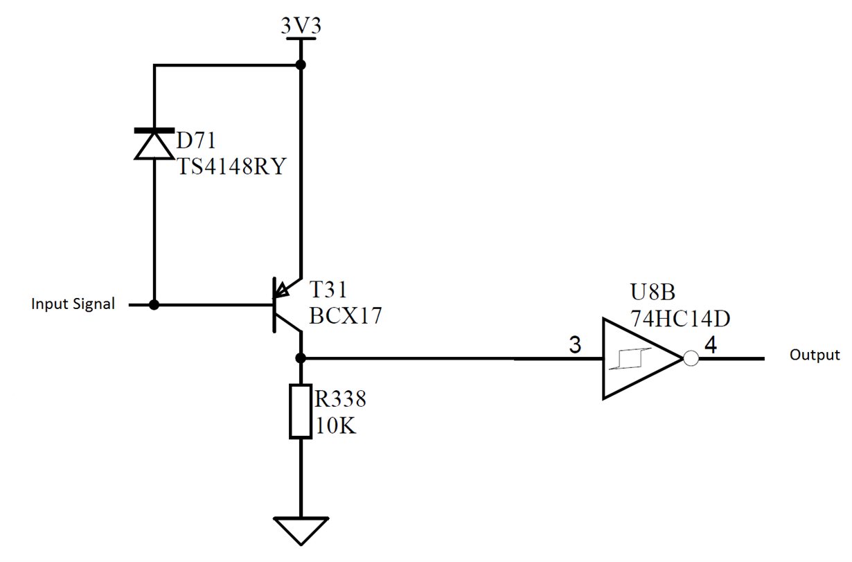
I'm guessing that there is something odd about the way I'm driving the input but I can't think what it could be.  I have a PNP transistor to 3.3V and a 10K resistor to ground.  I think it's happening as the transistor passes through it's linear region.

Can't work out how to post a picture here of my circuit.  I've got it in a work doc but the 'paste from word' just puts blanks in.

Any help appreciated

  • Hi Kevin,

    The best way I have found to post images on E2E is to save the image to my hard drive, then upload it with the "insert/edit media" button ( ).

    If you can post your schematic and an o-scope shot of the SN74HC14 input and output pins together, it would be very helpful for us to troubleshoot.

    At 3.3V, you should get about 0.3 V (minimum) of hysteresis, so a smoothly changing input shouldn't cause any oscillations.  I'm wondering if maybe the PNP amplifier is becoming an oscillator for a short time due to some resonance in the circuit.

  • Hi Emrys

    Here's the circuit

    Then input to the transistor is via a simple resistor divider from a 24V supply.

    When the 24V supply is turned off the 24V slowly decays and input signal slowly reduces.  When the input signal gets to about 2.7V the transistor starts to turn on which increases the voltage across R338 until the transistor is fully turned on at about 2V.

    I've tested this without the schmitt in the circuit and the voltage across the resistor is a straight line from 0V to 3.3V.

    Once I put the schmitt in place I get high frequency oscillation on both the input and the output.  the input oscillation appears to be between the two threshold levels.

    My theory is that when the schmitt input reaches the +ve threshold there is a small but significant current surge into the input which is enough to drop the input back down to the lower threshold level.

    Scope traces are tricky as the board is inside a machine.

    Kevin

  • I agree that this is a possibility. Do you have a capacitor from Vcc to GND placed near the SN74HC14?
  • Hi

    Yes I've got a decoupling cap (100nF) on the 3.3V supply pins of the 74HC14.  plus some 10uF caps around the board.

    if there is a current spike going into the input of the inverter would a small cap from the input to 0V be an idea so that the input has somewhere to source current from.

    Kevin

  • I would think that just adding a capacitor to the input would have little effect, but putting an RC filter there could slow the changes on the input enough to avoid oscillations.

    I'm thinking that the PNP circuit is heavily affected by the 3.3V rail changes (ie the input voltage doesn't change and neither does the threshold voltage, but the rail does).  Here's a simulation I ran just to see what would happen when the 3.3V rail oscillates while the base voltage rises:

    Red is the 3.3V rail (manually oscillated)

    Blue is the base voltage (linear increase)

    Green is the resistor voltage -- the result of the oscillation on the current output of the PNP

    I tried adding an RC filter to the input of the inverter with good results:

    The green line here is the filtered input to the inverter.