This thread has been locked.

If you have a related question, please click the "Ask a related question" button in the top right corner. The newly created question will be automatically linked to this question.

EMI test of CD74HC4051 & SN74HC4851 in automotive electronics

Other Parts Discussed in Thread: CD74HC4051, SN74HC4851-Q1, SN74HC4851

Hello,

There are 3 questions about the MUX.

1. Do you know which field strength level of BCI and RI CD74HC4051 can satisfy? Currently, the signals through MUX are disturbed when our ECUs with CD74HC4051 perform BCI(Bulk Current Injection test) and RI (Radiation Immunity test). 

2. Another MUX “SN74HC4851-Q1” has good performance against BCI and RI, since injection current control is implemented for  “SN74HC4851-Q1”. Do you know the detailed difference of CD74HC4051QPWRQ1 and SN74HC4851-Q1.

3. Could you also help to explain the mechanism of injection current control in SN74HC4851?

Thank you very much.

Bell

  • Hi Bell ,

    I will have to ask the design team and will have to search if there exists any documents about injection current control mechanism.
    The internal circuit wont be available but hopefully the idea of the implementation exists .
    Without current injection control feature , the BCI test would be expected to perform worse than the device with injection control . Will have to contact the quality team to get an answer about the RI and BCI testing . I am unsure ,however i believe out quality tests doesnt involve these tests.
  • Hi Shreyas,

    Thanks a lot for your answer.
    So there is no RI or BCI testing on the component level?
    Hope can get more information about the injection current control of the SN74HC4851 and the difference with CD74HC4051QPWRQ1.

    Thank you.

    Bell
  • Hi Bell ,

    We do no do RI / BCI on the component level , however , we may be doing it in a different name . We do latch up test , ESD(electrostatic discharge/EMI(electromagnetic interference) .
  • Hi Shreyas, 

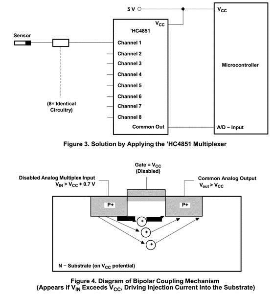
    For the component (HC4051) without the injection-current effect control, external diode/resistor networks are typically used to keep the analog channel signals within the supply-voltage range. Shown below

    The injection-current effect control allows signals at disabled analog input channels to exceed the supply voltage without affecting the signal of the enabled analog channel.

    Questions:

    1. Why an extra 6V regulator is needed in the Figure 2?
    2. Could you explain more on how the injection-current effect control works, please?


    Thank you.


    Bell